Al technical title is built by PatSnap Al team. It summarizes the technical point description of the patent document.
A hydraulic valve and windlass technology, applied in the field of hydraulic valves, can solve the problems of affecting the surrounding working environment, easy oil leakage at the joints, scattered installation of components, etc., and achieves the effects of complete functions, low production costs, and saving installation space
Inactive Publication Date: 2016-10-26
润琛液压机械南通有限公司
View PDF8 Cites 0 Cited by
Summary
Abstract
Description
Claims
Application Information
AI Technical Summary
This helps you quickly interpret patents by identifying the three key elements:
Problems solved by technology
Method used
Benefits of technology
Problems solved by technology
[0003] The purpose of the present invention is to provide a special hydraulic valve for windlass in order to solve the above problems, which solves the problem that the components of the existing marine windlass control valve block are relatively scattered when installed, and the combination takes up more space. At the same time, the joints of these combined components It is also easy to leak oil, which affects the surrounding working environment
Method used
Image
Click on the blue label to locate the original text in one second.
Reading with bidirectional positioning of images and text.
Examples
Embodiment Construction
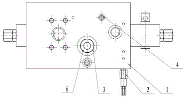
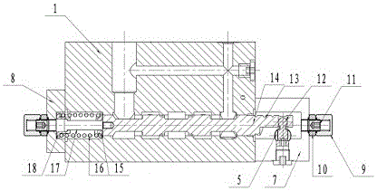
[0014] like figure 1 and figure 2 As shown, this specific embodiment adopts the following technical solutions: a special hydraulic valve for windlass, including a main valve body 1, a relief valve 2, a diverter valve core 3, a shuttle valve 4, an operating shaft 5, a spring 6, an end cover 17, end cover 2 8, cap nut 9, nut 10, limit screw 11, ball pin 12, valve core 13, connecting rod 14, spring seat 15, spring 2 16, pull rod 17 and spring seat 2 18 ; The main valve body 1 is provided with a relief valve 2, a shuttle valve 4, a diverter valve core 3 and a spring 6; the end cover 1 7 is fixedly connected to the lower right side of the main valve body 1; the end cover 2 8 is fixedly connected to the lower left side of the main valve body 1; there are two limit screw rods 11, and the limit screw rods 11 are fixedly connected to the outer sides of end cap one 7 and end cap two 8 through cap nut 9 and nut 10 respectively Central; the spool 13 is movably connected inside the lowe...
PUM
Abstract
The invention discloses a hydraulic valve dedicated to a windlass. The hydraulic valve comprises a main valve body, an overflow valve, a diverter valve core, a shuttle valve, an operating shaft, a spring I, an end cover I, an end cover II, cover type nuts, nuts, limiting screws, a circular ball pin, a valve core, a connecting rod, a spring seat I, a spring II, a pull rod and a spring seat II. According to the hydraulic valve, the structure is reasonable and simple, the production cost is low, and the mounting is convenient; the problems that during mounting, parts of a conventional ship windlass control valve block is relatively disperse and relatively occupies space after being combined, oil is liable to leak at the connection parts of the combination parts, and the surrounding working environment is influenced can be effectively solved; and the oil passing capacity is high, manual operation and remote hydraulic control operation manners can be applied, original universal multiway valves are highly integrated and combined in one valve block, the design is concise, the mounting space is greatly saved, and corrosion prevention and leakage prevention are facilitated after integration.
Description
Technical field: [0001] The invention relates to a hydraulic valve, in particular to a special hydraulic valve for windlass. Background technique: [0002] As we all know, hydraulic transmission technology is widely used in industrial and civil industries due to its large transmission force, flexible control, easy transmission and configuration. With the continuous development of hydraulic technology and the development trend of ships, hydraulic technology is more widely used in the field of ships, and The existing marine windlass control valve block includes a main valve block and a spool installed in it, a relief valve, a pressure compensation valve, a three-way shuttle valve, two fixed throttle plugs, a cut-off plug, a return spring, Operating mechanism, etc., but these parts are relatively scattered when installed, and the combination takes up more space. At the same time, the joints of these combined parts are prone to oil leakage, thereby affecting the surrounding work...
Claims
Application Information
Patent Timeline
Application Date:The date an application was filed.
Publication Date:The date a patent or application was officially published.
First Publication Date:The earliest publication date of a patent with the same application number.
Issue Date:Publication date of the patent grant document.
PCT Entry Date:The Entry date of PCT National Phase.
Estimated Expiry Date:The statutory expiry date of a patent right according to the Patent Law, and it is the longest term of protection that the patent right can achieve without the termination of the patent right due to other reasons(Term extension factor has been taken into account ).
Invalid Date:Actual expiry date is based on effective date or publication date of legal transaction data of invalid patent.