Eureka AIR delivers breakthrough ideas for toughest innovation challenges, trusted by R&D personnel around the world.

High-performance metal hard sealing butterfly valve

A metal sealing ring and hard sealing technology, applied in the direction of lift valves, valve devices, engine components, etc., can solve the problems of inseparability, increased maintenance costs, waste of resources, etc., to reduce maintenance man-hours and maintenance intensity and difficulty, reduce Maintenance cost, eliminate the effect of impervious to erosion

Inactive Publication Date: 2016-10-26
SHANGHAI KAIGONG VALVE CO LTD
View PDF6 Cites 1 Cited by
  • Summary
  • Abstract
  • Description
  • Claims
  • Application Information

AI Technical Summary

Problems solved by technology

[0002] At present, the most common hard-sealed butterfly valve is a three-eccentric multi-level structure. The butterfly valve seat is located on the valve body and cannot be disassembled and cannot be adjusted; the sealing ring is made of sheet stainless steel ring and graphite; The biggest disadvantage of this structure is that the valve has good sealing performance at the beginning of its use, but as the medium continuously washes away the sealing ring, the graphite will fall off, causing the valve to leak, and the failure of the sealing ring will cause the entire valve to be replaced. , wasted resources, and greatly increased maintenance costs; in addition, because it will be used under high temperature and high pressure, it is inevitable that there will be leakage. Therefore, how to reduce the leakage rate as much as possible and improve the safety performance of the valve needs to be improved and perfected.

Method used


Image

  • High-performance metal hard sealing butterfly valve
  • High-performance metal hard sealing butterfly valve

Examples


Embodiment Construction

[0019] In order to make the technical means, creative features, goals and effects achieved by the present invention easy to understand, the present invention will be further described below in conjunction with specific illustrations.

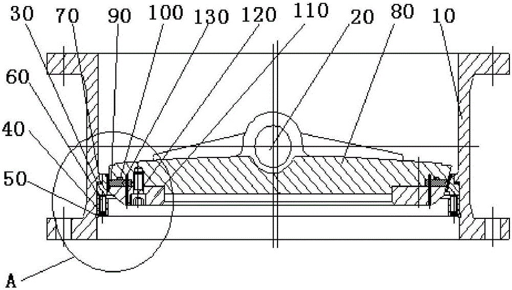
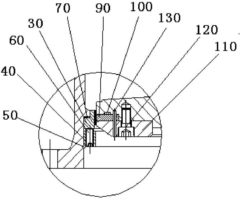
[0020] see figure 1 with figure 2 As shown, the present invention discloses a high-performance metal hard-sealed butterfly valve, including a valve body 10, a butterfly plate assembly, a valve stem 20, a valve seat 30, a valve seat pressure plate 40 and a retaining ring 50; the valve seat 30 passes through the valve seat pressure plate 40 and the hexagon socket flat-end set screw 60 are fixed on the inner wall of the valve, and a metal gasket 70 is arranged between the valve seat 30 and the adjacent plane of the valve body 10 to play a sealing role; at the same time, by adjusting the thickness of the metal gasket , to ensure the sealing specific pressure between the sealing surfaces, so as to effectively ensure the bidirectional sealing of the...


PUM


Abstract

The invention discloses a high-performance metal hard sealing butterfly valve which comprises a valve body, a butterfly plate assembly, a valve rod, a valve seat, a valve seat pressure plate and a retainer ring; the valve seat is fixed onto the inner wall of the valve body through the valve seat pressure plate and an inner hexagonal flat-end fastening bolt; a metal gasket is arranged between the valve seat and the plane adjacent to the valve body; the butterfly plate assembly comprises a butterfly plate, a metal sealing ring, a sealing ring gasket, a pressure plate, an inner hexagonal screw and a dowel pin; a groove is formed in the end surface on one side of the butterfly plate; the sealing ring gasket is arranged in the groove; the metal sealing ring is arranged between the butterfly plate and the pressure plate; and the pressure plate is used for fixing the metal sealing ring through the inner hexagonal screw. According to the high-performance metal hard sealing butterfly valve disclosed by the invention, the butterfly plate metal sealing ring and the butterfly plate are independent, and the valve body and the valve seat are also independent, so that two-way sealing is realized, the butterfly valve is not limited by a flow direction, and application of the butterfly valve is expanded; and moreover, the metal sealing ring on the butterfly plate and the valve seat can be independently replaced, and the valve is not needed to be integrally replaced, so that economic benefits are improved.

Description

technical field [0001] The invention relates to the field of butterfly valves, in particular to a high-performance metal hard seal butterfly valve. Background technique [0002] At present, the most common hard-sealed butterfly valve is a three-eccentric multi-level structure. The butterfly valve seat is located on the valve body and cannot be disassembled and cannot be adjusted; the sealing ring is made of sheet stainless steel ring and graphite; The biggest disadvantage of this structure is that the valve has good sealing performance at the beginning of its use, but as the medium continuously washes away the sealing ring, the graphite will fall off, causing the valve to leak, and the failure of the sealing ring will cause the entire valve to be replaced. , wasted resources, and greatly increased maintenance costs; in addition, because it will be used under high temperature and high pressure, it is inevitable that there will be leakage. Therefore, how to reduce the leakage ...

Claims


Application Information

Patent Timeline
Patent Type & Authority Applications(China)
IPC IPC(8): F16K1/22F16K1/228F16K1/42
CPCF16K1/22F16K1/2261F16K1/228F16K1/42
Inventor 王垂宏张加龄
Owner SHANGHAI KAIGONG VALVE CO LTD
Why Eureka
Eureka Blog
Learn More