Stator combined structure of cooling fan

A combined structure and fan stator technology, applied in the direction of magnetic circuit shape/style/structure, electric components, casing/cover/support, etc., can solve the problems of easy loosening, manufacturing and processing, high difficulty in assembly and positioning, and bonding strength Insufficient and other issues

Inactive Publication Date: 2016-10-26
SUZHOU FORCECON ELECTRIC
View PDF4 Cites 0 Cited by
  • Summary
  • Abstract
  • Description
  • Claims
  • Application Information

AI Technical Summary

Problems solved by technology

[0003] In the existing stator structure design of cooling fans, in order to fix the bearing contained in the shaft tube part, the industry usually uses a positioning component to assemble in the shaft tube part to achieve the purpose of pressing and fixing the bearing. However, due to the The assembly space faced by positioning components is quite small and narrow, so in fact, in addition to the high difficulty of component manufacturing and processing, assembly positioning and other aspects, the phenomenon of insufficient bonding strength and easy loosening is a common problem; moreover , since the current cooling fan must pass the standard verification of the mechanical shock project when it leaves the factory, this will increase the possibility of the aforementioned bearing positioning components getting loose, which will seriously affect the quality of the cooling fan

Method used


Image

  • Stator combined structure of cooling fan
  • Stator combined structure of cooling fan
  • Stator combined structure of cooling fan

Examples


Embodiment

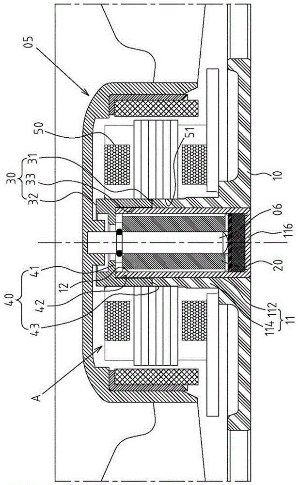
[0026] Example: see Figure 1~3 Shown are the preferred embodiments of the cooling fan stator combination structure of the present invention, but these embodiments are for illustration purposes only, and are not limited by this structure in patent application.

[0027] The stator A of the cooling fan is used for the rotor 05 shaft center 06 pivot group of the cooling fan (such as figure 1 shown), the combined structure of the cooling fan stator A includes:

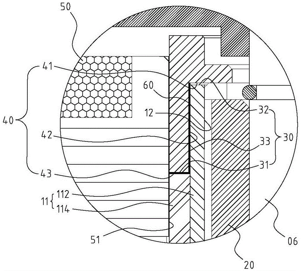
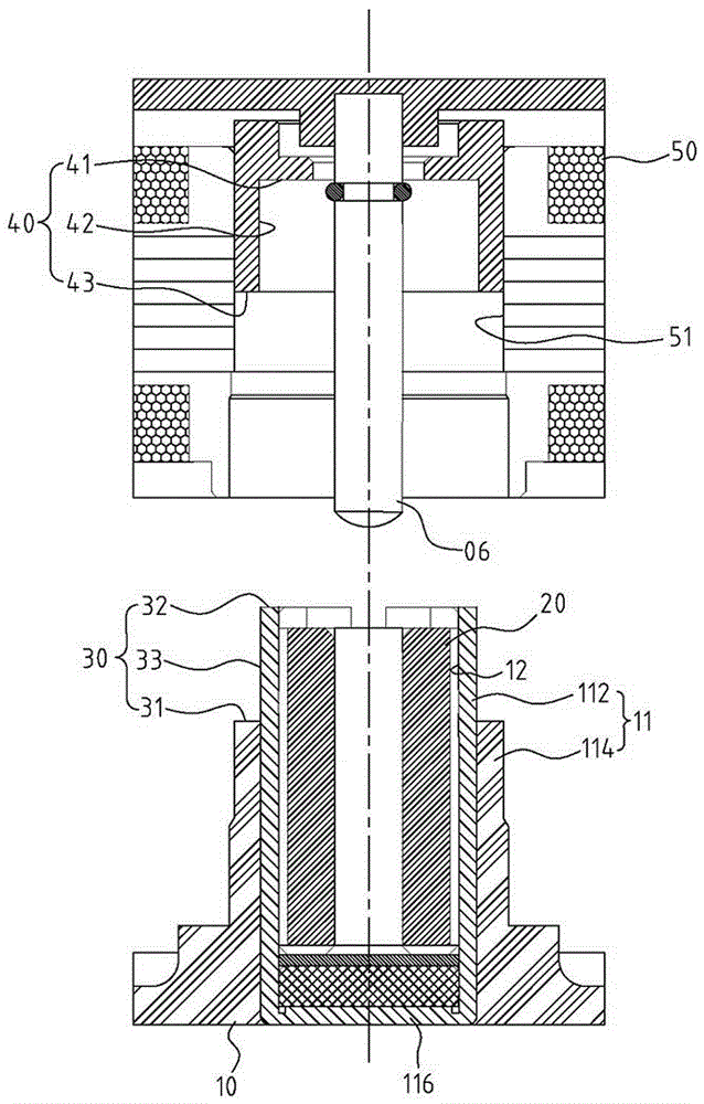
[0028] A base 10, the center of which is protrudingly provided with a shaft receiving part 11, and a receiving groove 12 is formed inside the shaft receiving part 11;

[0029] A bearing 20 is assembled in the accommodating groove 12 of the shaft receiving part 11;

[0030] A step-shaped joint positioning portion 30 is formed at the end of the shaft receiving portion 11. The step-shaped joint positioning portion 30 includes a first axial surface 31 and a second axial surface with an axial step difference. 32 and a radial...


PUM


Abstract

Provided is a stator combined structure of a cooling fan. The stator combined structure is characterized by comprising a base, a bearing, a stepped combination locating part, a pressing assembly and a coil set; a shaft pipe containing pipe part with a containing groove inside is arranged in the center of the base in a protruding manner; the bearing is assembled in the containing groove of the shaft pipe containing part; the stepped combination locating part is formed at the end of the shaft pipe containing part and at least comprises a reducing radial combination face; the pressing assembly comprises a pressing edge part and a radial combination edge part, the pressing edge part abuts against the end of the bearing, and the radial combination edge part and the radial combination face of the shaft pipe containing part are in sleeving fit; and the coil set is provided with a combination hole to be sleeve-combined and located to the periphery of the shaft pipe containing part of the base and the periphery of the pressing assembly. Therefore, by means of large-area combination morphology of the stepped combination locating part, the state that the pressing assembly abuts against and locates the bearing can achieve the practical progressiveness that firmness is improved better.

Description

technical field [0001] The invention relates to a cooling fan, in particular to an innovative structural space design of its stator combination structure. Background technique [0002] In terms of the structural composition of the cooling fan, it is mainly composed of a stator and a rotor that can rotate with the stator as a fulcrum. The stator is composed of multiple components, such as a base part, a shaft tube part, a bearing, a claw piece, and a coil. And so on, because the current electronic products have a trend of miniaturization, the structural design of the cooling fan must also meet the requirements of this miniaturized structure. Therefore, how to further simplify the components of the cooling fan to facilitate the miniaturization of the structural space Production and assembly operations have become the goal of the industry to think about breakthroughs. [0003] In the existing stator structure design of cooling fans, in order to fix the bearing contained in the...

Claims


Application Information

Patent Timeline
IPC IPC(8): F04D25/08H02K1/12H02K5/16
CPCF04D25/0646F04D25/062F04D25/0633F04D25/08H02K1/12H02K5/16
Inventor 张良升吴添进
Owner SUZHOU FORCECON ELECTRIC
Why Eureka
Try Eureka