Machining device for video camera
A processing device and camera technology, applied in metal processing equipment, manufacturing tools, grinding machines, etc., can solve problems such as low processing efficiency, and achieve the effect of improving quality and wide application range
- Summary
- Abstract
- Description
- Claims
- Application Information
AI Technical Summary
Problems solved by technology
Method used
Image

Examples
Embodiment 1
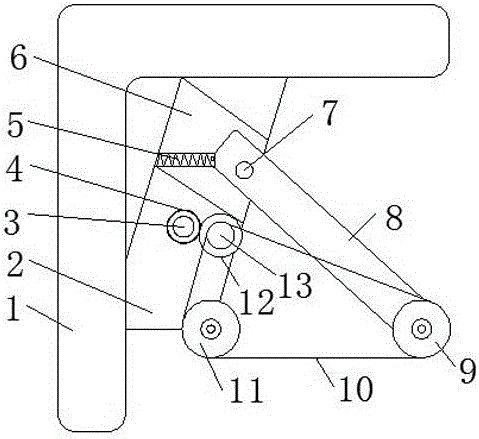
[0030]The camera processing device of this embodiment includes a manipulator, and a support frame is fixedly arranged on the manipulator, and the support frame includes a first support arm and a second support arm, and the second support arm is hinged on the first support arm , and the second support arm can rotate along the first support arm, the two sides of the end of the first support arm are respectively provided with a first guide roller and a second guide roller, the end of the second support arm A third guide roller and a fourth guide roller are respectively arranged on both sides of the guide roller, the axes of the first guide roller and the third guide roller are parallel to each other, and the axial directions of the second guide roller and the fourth guide roller are parallel to each other, so The outer end surface of the first guide roller is on the same vertical plane as the outer end surface of the third guide roller, the outer end surface of the second guide ro...
Embodiment 2
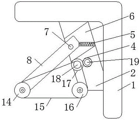
[0032] The camera processing device of this embodiment includes a manipulator, and a support frame is fixedly arranged on the manipulator, and the support frame includes a first support arm and a second support arm, and the second support arm is hinged on the first support arm , and the second support arm can rotate along the first support arm, the two sides of the end of the first support arm are respectively provided with a first guide roller and a second guide roller, the end of the second support arm A third guide roller and a fourth guide roller are respectively arranged on both sides of the guide roller, the axes of the first guide roller and the third guide roller are parallel to each other, and the axial directions of the second guide roller and the fourth guide roller are parallel to each other, so The outer end surface of the first guide roller is on the same vertical plane as the outer end surface of the third guide roller, the outer end surface of the second guide r...
Embodiment 3
[0034] The camera processing device of this embodiment includes a manipulator, and a support frame is fixedly arranged on the manipulator, and the support frame includes a first support arm and a second support arm, and the second support arm is hinged on the first support arm , and the second support arm can rotate along the first support arm, the two sides of the end of the first support arm are respectively provided with a first guide roller and a second guide roller, the end of the second support arm A third guide roller and a fourth guide roller are respectively arranged on both sides of the guide roller, the axes of the first guide roller and the third guide roller are parallel to each other, and the axial directions of the second guide roller and the fourth guide roller are parallel to each other, so The outer end surface of the first guide roller is on the same vertical plane as the outer end surface of the third guide roller, the outer end surface of the second guide r...
PUM
 Abstract
Description
Claims
Application Information
 - Generate Ideas
- Intellectual Property
- Life Sciences
- Materials
- Tech Scout
- Unparalleled Data Quality
- Higher Quality Content
- 60% Fewer Hallucinations
Browse by: Latest US Patents, China's latest patents, Technical Efficacy Thesaurus, Application Domain, Technology Topic, Popular Technical Reports.
© 2025 PatSnap. All rights reserved.Legal|Privacy policy|Modern Slavery Act Transparency Statement|Sitemap|About US| Contact US: help@patsnap.com