An impact-resistant slide

An impact-resistant, sliding rail technology, applied in the hardware field, can solve the problems of easy deviation, violent impact, poor buffer performance of the sliding rail, etc., and achieve the effect of improving the overall strength, reducing the deformation probability, and improving the buffer effect.

Active Publication Date: 2018-11-06
HAINING JINMAO HARDWARE
View PDF9 Cites 0 Cited by
  • Summary
  • Abstract
  • Description
  • Claims
  • Application Information

AI Technical Summary

Problems solved by technology

[0004] The existing slide rail has a large contact area when sliding, so the friction force generated is also relatively large, which not only makes the slide rail wear more serious, but also produces relatively large noise, and due to the large friction force, the sliding is not smooth, and it is easy to occur Misalignment, causing misalignment and jamming, etc., which affects daily use
[0005] Unsmooth sliding is likely to cause continuous inconvenience. Due to the unsmooth sliding, the user generally exerts a large force when pushing and pulling. When closing, the cushioning performance of the slide rail is poor, and the impact resistance is weak, which is easy to cause violent impact. , which produces a lot of noise, and will affect the strength of the slide rail in the long run, resulting in deformation of the slide rail
In addition, it is easy to pull the drawer out due to excessive force when it is opened, causing the drawer to fall

Method used


Image

  • An impact-resistant slide
  • An impact-resistant slide
  • An impact-resistant slide

Examples


Embodiment Construction

[0028] The following are specific embodiments of the present invention and in conjunction with the accompanying drawings, the technical solutions of the present invention are further described, but the present invention is not limited to these embodiments.

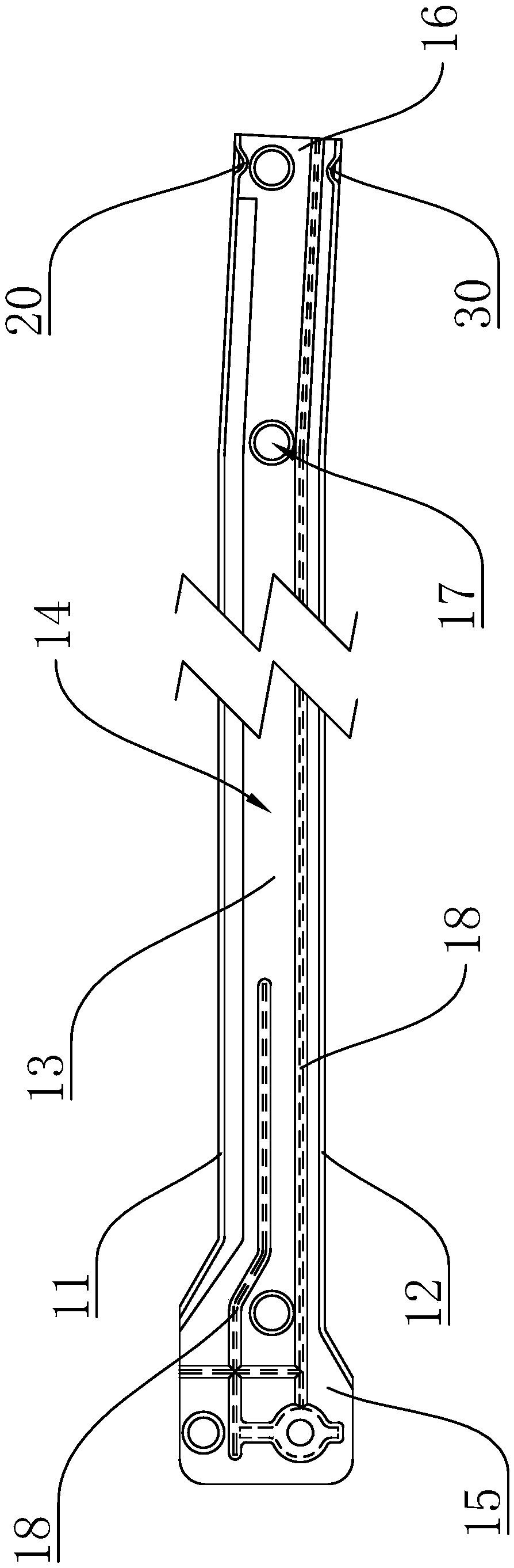
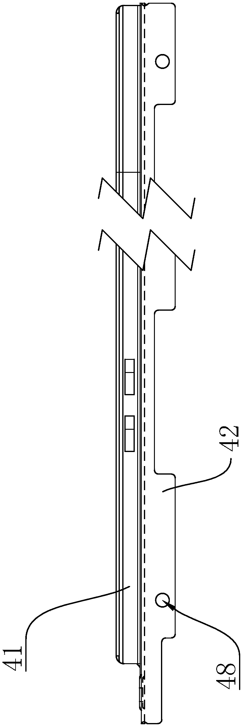
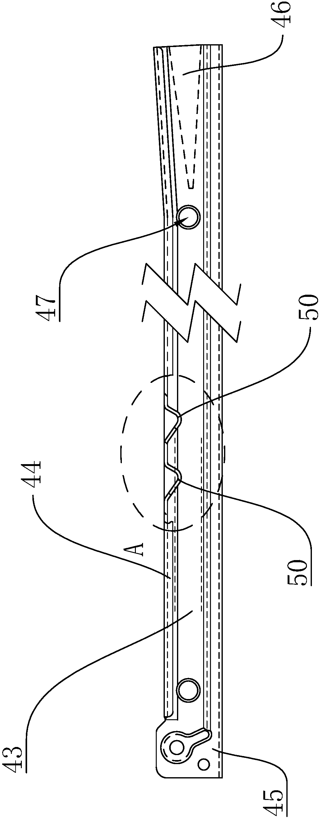
[0029] Such as Figure 1 to Figure 5 As shown, the present invention provides an impact-resistant slide rail, including a static rail fixed on the cabinet body and a moving rail fixed on the drawer, and the static rail includes an integrally formed top plate-11, bottom plate-12 and side plates- 13. The side plate 13 connects the top plate 11 and the bottom plate 12. The top plate 11, the bottom plate 12 and the side plate 13 are stamped to form a chute 14, and the side plate 13 is used to fix the cabinet body; the static rail has a static rail The first end 15 and the second end 16 of the static rail, the first end 15 of the static rail is used to install the first pulley; 43 connects top plate 2 41 and bottom plate 2 42,...


PUM


Abstract

The invention provides an impact-resistant slide rail which comprises a static rail and a movable rail. The static rail comprises a first top plate, a first bottom plate and a first side plate, a slide groove can be formed after the first top plate, the first bottom plate and the first side plate are stamped, and the first side plate is used for being fixed to a cabinet; the static rail is provided with a first end of the static rail and a second end of the static rail, and the first end of the static rail is used for mounting a first pulley; the movable rail comprises a second top plate, a second bottom plate and a second side plate, the second side plate is used for being fixed with a side plate of a drawer, the second bottom plate is used for being fixed to a bottom plate of the drawer, and an upper flange downwardly extends out of the second top plate; the movable rail is provided with a first end of the movable rail and a second end of the movable rail, the first end of the movable rail is used for mounting a second pulley, the second pulley can be embedded in the slide groove and can roll along the slide groove, and the first pulley can be embedded into a space between the upper flange, the second top plate and the second side plate and can carry out rolling friction relative to the movable rail; at least two protrusions with limiting and buffering effects are formed on the inner wall of the second top plate and are of asymmetric structures, and every two adjacent protrusions are separated from each other by a preset distance.

Description

technical field [0001] The invention belongs to the technical field of hardware and relates to a slide rail, in particular to an impact-resistant slide rail. Background technique [0002] The slide rail is a hardware connecting part fixed on the cabinet body of the furniture for the drawer or cabinet board of the furniture to move in and out. The slide rail is suitable for the drawer connection of wooden and steel drawers such as cabinets, furniture, office cabinets, and bathroom cabinets. [0003] At present, there are mainly three types of slide rails: roller type, steel ball type, and gear type. The roller type drawer slide rail has the advantages of simple structure and low noise. It is mainly composed of rollers and two rails, which can meet the daily push and pull needs. [0004] The existing slide rail has a large contact area when sliding, so the friction force generated is also relatively large, which not only makes the slide rail wear more serious, but also produce...

Claims


Application Information

Patent Timeline
Patent Type & Authority Patents(China)
IPC IPC(8): A47B88/57A47B88/493
CPCA47B2210/0018
Inventor 褚才国褚一新项炳法杜国恒蔡瑜洁赵旭
Owner HAINING JINMAO HARDWARE
Why Eureka
Try Eureka