


Quick Research
Generate reliable direction feasibility study reports for your R&D in just a few steps.

Technical Q&A
Discover and master advanced knowledge NOW. Basics, ideas, possibilities, all at once.

Find Solutions
As an expert in R&D theories, this can generate solutions to your technical problems instantly.

Evaluate Feasibility
Analyze your overall solution with one click, know your potential R&D risks in advance.

Monitor Landscape
Get weekly tech updates, stay abreast of the latest tech innovations and key insights.
Sour gas combustion using in-situ oxygen production and chemical looping combustion
A technology of chemical chain combustion and acid gas, which is applied in the direction of fuel burning in molten state, fluidized bed combustion equipment, oxygen/ozone/oxide/hydroxide, etc., which can solve the problem of no high cost and avoid direct contact , fully transformed effect
- Summary
- Abstract
- Description
- Claims
- Application Information
AI Technical Summary
Benefits of technology
Problems solved by technology
Method used
Image

Examples
Embodiment Construction
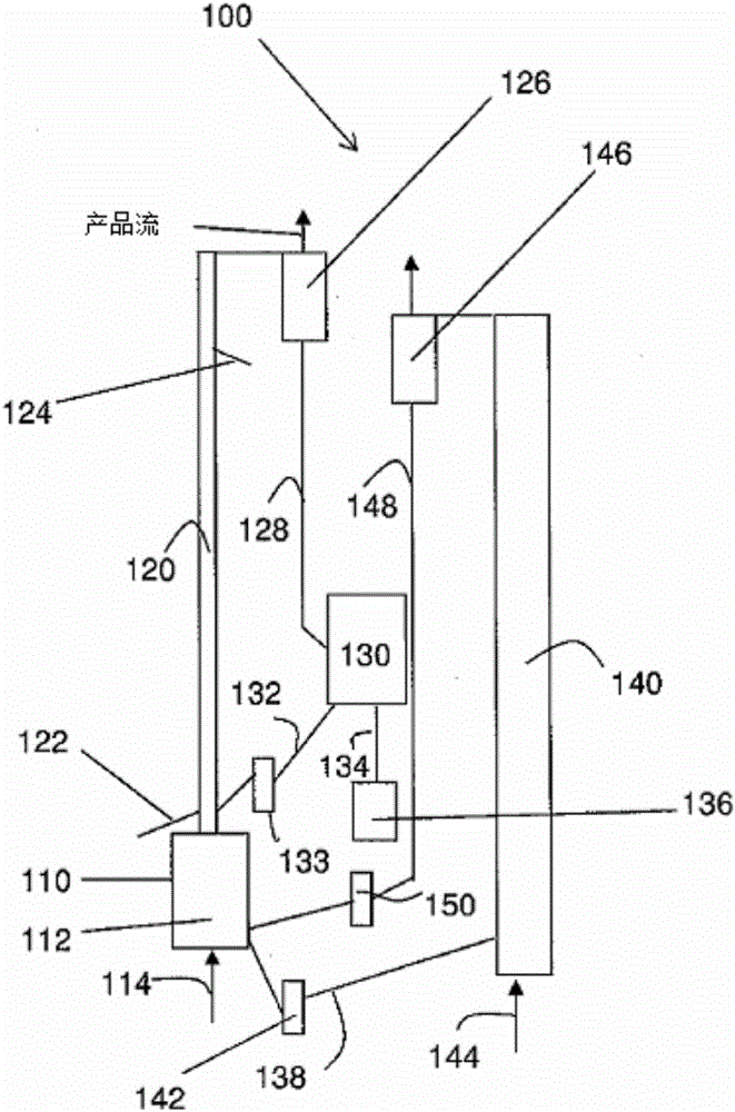
[0017] As mentioned earlier, chemical looping combustion (CLC) usually employs a dual fluidized bed system (circulating fluidized bed process) in which metal oxides are used as bed materials to provide fuel in the reactor. Oxygen for combustion. The reduced metal oxides are then transferred to the second bed (air reactor) and re-oxidized and reintroduced back to the fuel reactor to complete the cycle. Therefore, chemical looping combustion (CLC) uses two or more reactions to complete the oxidation of hydrocarbon fuels. In its simplest form, an oxygen-carrying species (usually a metal) is first oxidized in air to form an oxide. Then, the oxide is reduced by the hydrocarbon as reducing agent in the second reaction.
[0018] The CLC process of the present invention aims to overcome the deficiencies associated with traditional CLC processes of acid gas combustion. As stated, unlike conventional CLC processes where the acid gas is in direct contact with the oxygen carrier (e.g.,...
PUM
 Abstract
Description
Claims
Application Information
 - R&D Engineer
- R&D Manager
- IP Professional
- Industry Leading Data Capabilities
- Powerful AI technology
- Patent DNA Extraction
Browse by: Latest US Patents, China's latest patents, Technical Efficacy Thesaurus, Application Domain, Technology Topic, Popular Technical Reports.
© 2024 PatSnap. All rights reserved.Legal|Privacy policy|Modern Slavery Act Transparency Statement|Sitemap|About US| Contact US: help@patsnap.com