Hybrid vehicle control device
A hybrid vehicle and control device technology, applied in hybrid vehicles, power units, pneumatic power units, etc., can solve problems such as inability to reduce torque, and achieve the effect of avoiding torque shock
- Summary
- Abstract
- Description
- Claims
- Application Information
AI Technical Summary
Problems solved by technology
Method used
Image

Examples
no. 1 Embodiment approach >
[0067] refer to Figure 1 to Figure 13 , the hybrid vehicle control device according to the first embodiment will be described.
[0068]
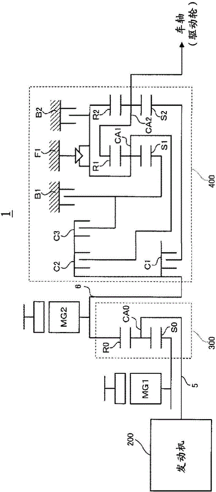
[0069] First, refer to figure 1 , the overall structure of the hybrid vehicle 1 (in particular, the structure of the drive mechanism) of the present embodiment will be described. here, figure 1 It is a block diagram showing the overall configuration of the hybrid vehicle according to the first embodiment.
[0070] Such as figure 1 As shown, the hybrid vehicle 1 according to the present embodiment is configured as a hybrid vehicle in which a plurality of power sources are combined. Specifically, hybrid vehicle 1 has engine 200 , motor generator MG1 , and motor generator MG2 as power sources for traveling.
[0071] Engine 200 functions as a main power source of hybrid vehicle 1 and is a gasoline engine as an example of the "internal combustion engine" of the present invention.
[0072] Motor generators MG1 and MG2 have a work function...
no. 2 Embodiment approach >
[0138] Next, refer to Figure 14 ~ Figure 16 , the hybrid vehicle control device according to the second embodiment will be described. In addition, the second embodiment differs from the above-mentioned first embodiment only in a part of operations, and the other operations and device configurations are substantially the same. Therefore, in the following, parts different from those of the first embodiment will be described in detail, and descriptions of overlapping parts will be appropriately omitted.
[0139]
[0140] First, refer to Figure 14 , the operation of the hybrid vehicle control device according to the second embodiment will be described. here, Figure 14 It is a flowchart showing the operation of the hybrid vehicle control device according to the second embodiment.
[0141] exist Figure 14 Here, when the control device for the hybrid vehicle according to the second embodiment is in operation, the HVECU 60 predicts the shifting by the transmission 400 (step...
no. 3 Embodiment approach >
[0156] Next, refer to Figure 17 A control device for a hybrid vehicle according to a third embodiment will be described. In addition, the third embodiment differs only in a part of operations from the above-mentioned first and second embodiments, and other operations and / or device configurations are substantially the same. Therefore, in the following, parts different from those of the first and second embodiments will be described in detail, and descriptions of overlapping parts will be appropriately omitted.
[0157]
[0158] First, refer to Figure 17 , the operation of the hybrid vehicle control device according to the third embodiment will be described. here, Figure 17 It is a flowchart showing the operation of the hybrid vehicle control device according to the third embodiment.
[0159] exist Figure 17 Here, when the control device for the hybrid vehicle according to the third embodiment is in operation, the HVECU 60 predicts the shifting by the transmission 400...
PUM
 Abstract
Description
Claims
Application Information
 - R&D
- Intellectual Property
- Life Sciences
- Materials
- Tech Scout
- Unparalleled Data Quality
- Higher Quality Content
- 60% Fewer Hallucinations
Browse by: Latest US Patents, China's latest patents, Technical Efficacy Thesaurus, Application Domain, Technology Topic, Popular Technical Reports.
© 2025 PatSnap. All rights reserved.Legal|Privacy policy|Modern Slavery Act Transparency Statement|Sitemap|About US| Contact US: help@patsnap.com