Current sharing circuit based on LED voltage-boosting constant current drive

A constant current drive and circuit technology, applied in the field of dual-channel parallel drive control circuits, can solve the problems that the voltage characteristics of two LED strings cannot be guaranteed, the existence of LED string current errors, and software parameters need to be redesigned, etc., to achieve a wide range of use, Timely response, simple production and maintenance

Inactive Publication Date: 2016-10-12
HASCO VISION TECHNOLOGY CO LTD
View PDF6 Cites 4 Cited by
  • Summary
  • Abstract
  • Description
  • Claims
  • Application Information

AI Technical Summary

Problems solved by technology

[0009] However, since the voltage characteristics of each LED are random, the value of the simulated load is not fixed. In order to facilitate production and save costs, the simulated load can only use approximate values. The method of using simulated loads cannot guarantee the voltage of two LED strings The characteristics are truly consistent, and the current error through the two LED strings still exists
On the other hand, the use of MCU control not only has high hardware costs, but also requires software development, which increases labor costs; the current parameters of current sampling are related to the LED load. After the load changes, the software parameters need to be redesigned, and the versatility is not strong.

Method used


Image

  • Current sharing circuit based on LED voltage-boosting constant current drive
  • Current sharing circuit based on LED voltage-boosting constant current drive
  • Current sharing circuit based on LED voltage-boosting constant current drive

Examples


Embodiment Construction

[0041] In order to better understand the above technical solutions of the present invention, a further detailed description will be given below in conjunction with the drawings and embodiments.

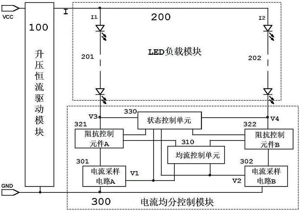
[0042] The principle block diagram of the current sharing circuit based on LED boost constant current drive of the present invention is as follows: figure 1 As shown, it consists of a boost constant current drive module 100, an LED load module 200 and a current sharing control module 300. The boost constant current drive module 100 is connected to the vehicle low-voltage DC power supply to provide constant current for the LED load module 200. drive current;

[0043] The LED load module 200 is composed of an LED string A 201 and an LED string B 202, the positive ends of the LED string A 201 and the LED string B 202 are connected in parallel to the constant current drive current output end of the boost constant current drive module 100, and the LED The negative ends of the string A 201...


PUM


Abstract

The invention discloses a current sharing circuit based on LED voltage-boosting constant current drive, relates to a driving circuit used for a vehicle LED illuminating apparatus and component configuration, and particularly relates to a double-circuit parallel drive control circuit used for an LED voltage-boosting constant current driven automotive lamp light source; the current sharing control module comprises a current sampling circuit, a current sharing control unit and an impedance control element; the two input ends of the current control circuit are connected to the current sampling circuit and a current sharing reference signal generation circuit separately; by comparing a current sharing reference signal with a current sampling signal, an impedance control signal is generated and transmitted to the impedance control element; by automatically adjusting the impedance value of the impedance control element, the current sharing control of the two parallel LED string current sharing branches is realized; the current sharing of the two constant current driven LED strings can be realized under different numbers of the two LED strings, or different voltage characteristics, or inconsistent voltage drop of the two LED strings; and whether the brands and the characteristics of the LEDs are the same or not, the consistency of the current values and the rapid response of the state control can be ensured.

Description

technical field [0001] The invention relates to the arrangement of general vehicle lighting or signaling devices, and in particular to a dual-channel parallel drive control circuit for LED boosting and constant current driving vehicle light sources. Background technique [0002] With the development of LED technology, the performance of LED has been continuously improved, but the price has been falling. LED lights, which were only seen on high-end cars before, are gradually becoming popular in low-end and mid-range cars. LED has the characteristics of safety, reliability, environmental protection, energy saving, beauty, fashion, etc., and has been used in automobile tail lights, fog lights, signal lights, high and low beam lights, interior lights and other fields. [0003] Chinese invention patent "A Linear Constant Current Even Current LED Drive Circuit and Its Circuit Board Structure" (invention patent number: ZL201210426006.6 authorized announcement number: CN102905443B) ...

Claims


Application Information

Patent Timeline
Patent Type & Authority Applications(China)
IPC IPC(8): H05B33/08H05B44/00H05B45/10H05B45/30H05B45/345
CPCH05B45/00H05B45/46
Inventor 谢国华夏盛
Owner HASCO VISION TECHNOLOGY CO LTD
Why Eureka
Try Eureka