
Train main and auxiliary integrated traction converter capable of being axially controlled independently

A technology of traction converters and converters, which is applied in the direction of converting AC power input into AC power output, output power conversion devices, electrical components, etc. The problem of heavy weight of the converter is achieved, which is conducive to structural layout and lightweight design, adding auxiliary grounding protection and charging functions in the warehouse, and reducing weight

Active Publication Date: 2016-10-12
ZHUZHOU CSR TIMES ELECTRIC CO LTD
View PDF7 Cites 14 Cited by
  • Summary
  • Abstract
  • Description
  • Claims
  • Application Information

AI Technical Summary

Problems solved by technology

However, there are too many devices on the main circuit, which leads to the heavy weight of the converter, and the parallel connection of the intermediate circuit makes the structural layout troublesome. At the same time, complete axis control cannot be realized in the control. When a serious fault occurs, the fault will often expand and the normal converter unit will also be lost. function, the auxiliary converter is directly connected to the intermediate circuit, when the main converter fails, it often affects its normal operation, and in turn, its failure will also affect the operation of the main converter

Method used


Image

  • Train main and auxiliary integrated traction converter capable of being axially controlled independently
  • Train main and auxiliary integrated traction converter capable of being axially controlled independently
  • Train main and auxiliary integrated traction converter capable of being axially controlled independently

Examples


Embodiment Construction

[0026] The present invention will be further described in detail below with reference to the drawings and specific embodiments of the specification.

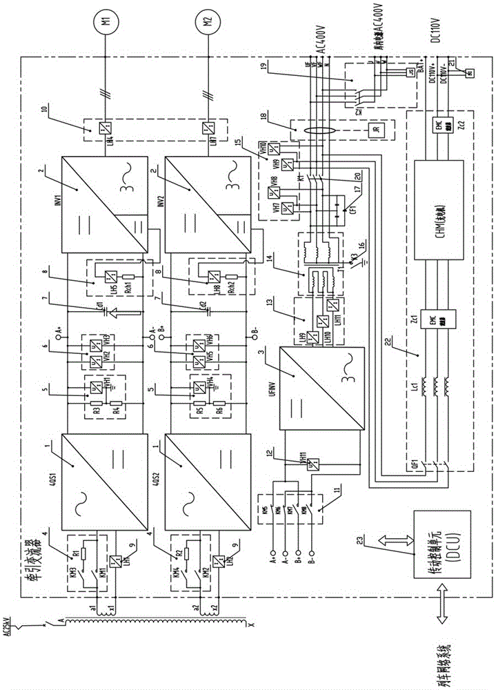
[0027] Such as figure 1 As shown, the train main and auxiliary integrated traction converter with independent axis control of the present invention includes two completely independent converter units and an auxiliary inverter 3. The auxiliary inverter 3 is used for switching through the auxiliary inverter. The cutting device 11 is freely switched on and off in the intermediate DC link 7 of the double converter, and its back end is connected with an auxiliary transformer 14 to provide electrical energy for the charger and auxiliary load after voltage reduction; each converter unit includes:

[0028] Four-quadrant rectifier 1, used for AC-DC conversion of single-phase AC power in the pantograph network;

[0029] The main inverter 2 is used to change the intermediate direct current into three-phase alternating current for the traction mot...


PUM


Abstract

Disclosed is a train main and auxiliary integrated traction converter capable of being axially controlled independently. The train main and auxiliary integrated traction converter comprises two converter units which are independent completely, and an auxiliary inverter, wherein the auxiliary inverter is used for performing free switching in the intermediate link of the two converters through an auxiliary inverter switching apparatus; the back end of the auxiliary inverter is connected with an auxiliary transformer; after voltage drop is performed, the auxiliary inverter supplies electric energy to a charger and an auxiliary machine load; each converter unit comprises a four-quadrant rectifier which is used for performing alternating current-direct current conversion on the bow net single-phase alternating current, a main inverter which is used for converting the intermediate direct current into three-phase alternating current for a traction motor, a charging short-circuited circuit which is used for ensuring the charging and the normal operation of the converters, a grounding detecting unit which is used for monitoring the grounding conditions of each place of the main circuit of the traction converter, and a chopping unit which is used for carrying out overvoltage suppression and rapid discharging in the intermediate link. The train main and auxiliary integrated traction converter has the advantages of simple and compact structure, easy implementation, high reliability and the like.

Description

Technical field [0001] The invention mainly relates to the field of locomotive traction converters, and particularly refers to a train main and auxiliary integrated traction converter capable of independent axle control. Background technique [0002] The application prospects of domestic and foreign EMUs are broad, and there are continuous EMU products or concepts with higher reliability, better safety performance, better comfort performance, and better cost performance. A few developed countries have already mastered a complete set of mature EMU products. technology. At present, the world-wide train market is huge, and EMUs will likely become the main rail transportation tools in most countries. Large-scale construction of high-speed rail lines and intercity EMU lines is being carried out in various parts of our country, which will help ease regional traffic pressure and low-carbon travel. As the power source of the EMU, the traction converter has very important technical and e...

Claims


Application Information

Patent Timeline
IPC IPC(8): H02M5/48
CPCH02M5/48
Inventor 李华刘永江荣智林忻力陈斌左鹏龚昱刘大祁善军唐雄辉吴刚
Owner ZHUZHOU CSR TIMES ELECTRIC CO LTD
Learn More