
Automatic conduit moving and overturning mechanism

An automatic moving and flipping mechanism technology, which is applied in the direction of cable installation devices, electrical components, equipment for dismantling/armouring cables, etc., can solve the problems of sagging tail wires, easily damaged wire cores, easily damaged wires, etc., and achieve reasonable design, The effect of simple structure

Active Publication Date: 2016-10-12
徐州领君自动化设备有限公司
View PDF8 Cites 1 Cited by
  • Summary
  • Abstract
  • Description
  • Claims
  • Application Information

AI Technical Summary

Problems solved by technology

[0002] With the development of society and the advancement of industrial technology, the demand for wire stripping machines in the market is increasing, and the technical requirements for wire stripping are also getting higher and higher. It cannot reach 200mm, and when processing a long stripping head, there is no supporting plate, which makes the tail end line droop, and the wire core is easy to be damaged when stripping
When stripping after the existing wire stripping machine, the guide tube rotates upwards, the guide plate is facing the knife edge, the wire is poured into the guide plate backwards, and the line sags due to the effect of gravity. The wire is easy to be damaged, and the stripping length of the tail end cannot reach 200mm

Method used


Image

  • Automatic conduit moving and overturning mechanism
  • Automatic conduit moving and overturning mechanism
  • Automatic conduit moving and overturning mechanism

Examples


Embodiment Construction

[0014] The present invention will be further described below in conjunction with the accompanying drawings.

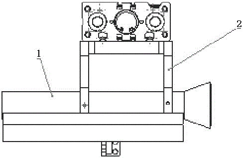
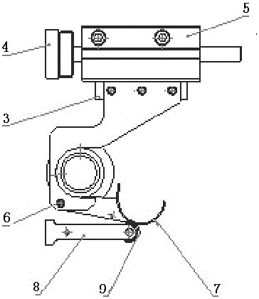
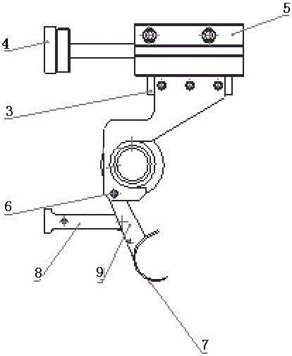
[0015] Depend on Figure 1-4 It can be seen that a conduit automatic moving and turning mechanism includes a cylinder 5, a cylinder mounting plate 4, a conduit 1, a conduit seat 2, a mounting plate 3, a rotating rod 6, a material guide groove 7, a bearing 9 and a bearing mounting seat 8. The conduit 1 is fixed on the conduit base 2, the conduit base 2 is installed on the mounting plate 3, the cylinder 5 is fixed on the mounting plate 3 and the cylinder mounting plate 4, the guide groove 7 passes through the rotating rod 6 and is connected to the conduit base 2, and the guide Feed chute 7 can rotate freely, and bearing 9 is installed on the bearing mount 8, and bearing 9 supports feed chute 7.

[0016] Wherein the cylinder mounting plate 4 is fixed on the panel, when the cylinder 5 stretches out, as image 3 At this time, the center of the catheter is aligned with the...


PUM


Abstract

The invention relates to an automatic conduit moving and overturning mechanism which comprises a cylinder, a cylinder installing plate, a conduit, a conduit base, an installing plate, a rotary rod, a material guiding slot, a bearing and a bearing mounting base, wherein the conduit is fixed on the conduit base, the conduit base is installed on the installing plate, the cylinder is fixed on the cylinder installing plate, the material guiding slot passes through the rotary rod and is connected to the conduit base, the material guiding slot is supported by the bearing, and the bearing is installed on the bearing mounting base. The automatic conduit moving and overturning mechanism is simple in structure and reasonable in design, and switching of the conduit and the material guiding slot, wire delivery and front end peeling are realized through cylinder movement. The conduit is used for cutting total length, and the material guiding slot is used for peeling the rear end. A wire rod is dragged to prevent the wire rod from drooping due to deadweight. The material guiding slot is in two different states at two different positions. The wire rod is dragged during peeling the rear end, and peels peeled off from the wire rod can fall down timely. The tail end peeling length reaches 200mm.

Description

technical field [0001] The invention relates to an automatic moving and turning mechanism for a catheter, which belongs to the technical field of wire stripping machines. Background technique [0002] With the development of society and the advancement of industrial technology, the demand for wire stripping machines in the market is increasing, and the technical requirements for wire stripping are also getting higher and higher. It cannot reach 200mm, and when processing a long stripped head, there is no supporting plate, which makes the tail end line droop, and the line core is easy to be damaged when stripping. When stripping after the existing wire stripping machine, the guide tube rotates upwards, the guide plate is facing the knife edge, the wire is poured into the guide plate backwards, and the line sags due to the effect of gravity. It is easy to damage the wire, and the stripping length at the end cannot reach 200mm. Contents of the invention [0003] The object ...

Claims


Application Information

Patent Timeline
Patent Type & Authority Applications(China)
IPC IPC(8): H02G1/12
CPCH02G1/1248
Inventor 刘君
Owner 徐州领君自动化设备有限公司
Learn More