
Hypersonic air vehicle reentry trajectory optimization method based on reentry point parameter

A hypersonic, re-entry trajectory technology, used in instruments, vehicle position/route/altitude control, non-electric variable control, etc. It can solve the problem of long optimization time, inability to guarantee global optimality, separate design of longitudinal trajectory and lateral trajectory, etc. question

Active Publication Date: 2016-10-12
NAT UNIV OF DEFENSE TECH
View PDF2 Cites 32 Cited by
  • Summary
  • Abstract
  • Description
  • Claims
  • Application Information

AI Technical Summary

Problems solved by technology

[0007] The purpose of the present invention is to provide a hypersonic vehicle re-entry trajectory optimization method based on re-entry point parameters. This invention solves the problem that the optimization time is too long in the re-entry trajectory optimization process in the prior art, and the longitudinal trajectory and lateral trajectory need to be designed separately. , technical problems that cannot guarantee global optimality or require model simplification to quickly optimize

Method used


Image

  • Hypersonic air vehicle reentry trajectory optimization method based on reentry point parameter
  • Hypersonic air vehicle reentry trajectory optimization method based on reentry point parameter
  • Hypersonic air vehicle reentry trajectory optimization method based on reentry point parameter

Examples


example 1

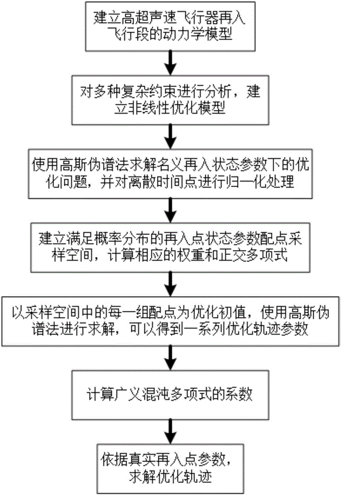
[0073] Example 1 Calculate the output variable of the optimized trajectory according to the state parameters of the re-entry point for use by the guidance system, that is, the output variable Y=[r, λ, φ, V, θ, σ, t in step S700 f ,J m ].

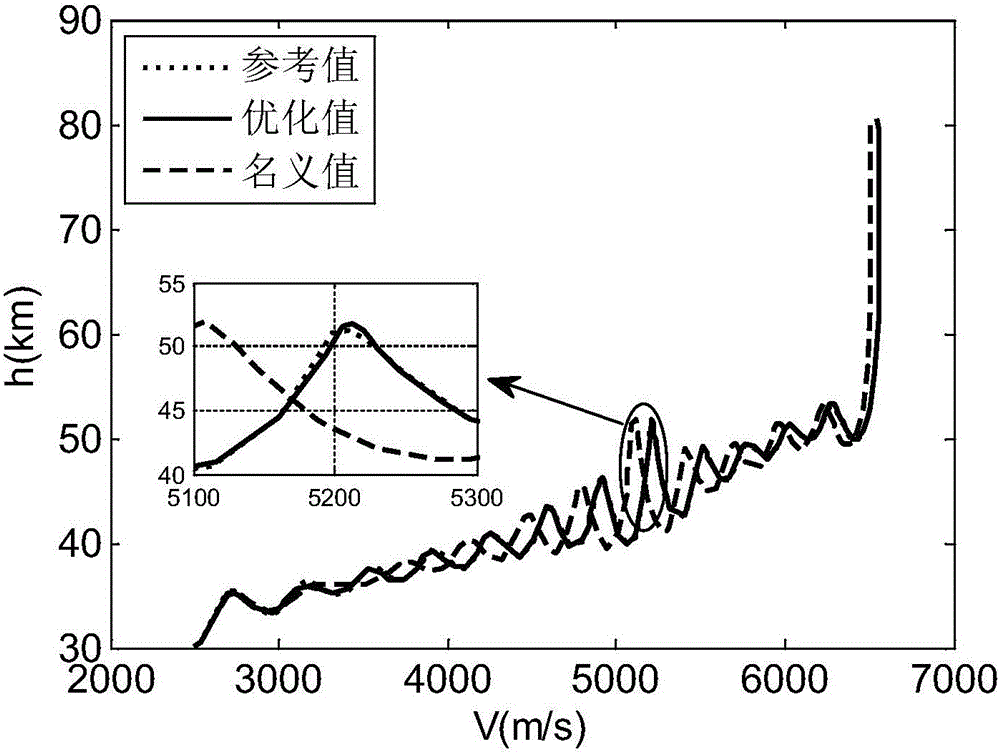
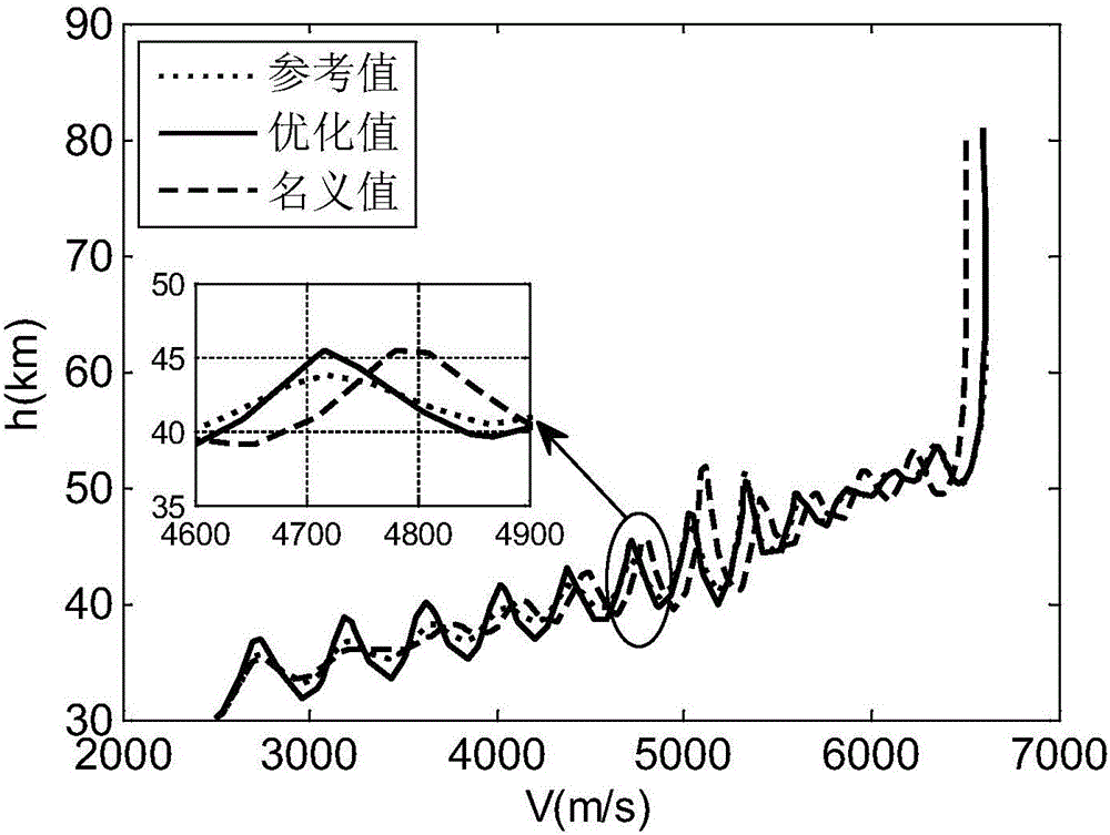
[0074] This example studies the trajectory optimization results of three uncertainty levels, |k i |=1,2,3. In the example, "reference value" represents the optimization result using the Gaussian pseudospectral method with the actual re-entry point state parameter as the initial value, and "optimized value" represents the use of the present invention based on the re-entry point parameter uncertainty expansion method to obtain the actual re-entry point The state parameter is the optimized trajectory obtained from the initial value, and the "nominal value" means the optimization result calculated offline using the Gaussian pseudospectral method with the initial value of the state parameter at the nominal re-entry point.

[0075] Figure 2~4...

example 2

[0080] Example 2 Calculate the control variables of the optimized trajectory according to the state parameters of the re-entry point for use by the control system, that is, the output variable Y=[θ, σ, t in step S700 f ,Jm ].

[0081] Study the worst case of optimization results in Example 2 (uncertainty level|k i |=3), use the method provided by the present invention to calculate the optimal control variable, then add the optimal control variable to the dynamic equation, integrate to obtain the motion state, and compare the state parameter and the control parameter.

[0082] The result is as Figure 5-6 As shown, the height versus time curves and the variation laws of the horizontal motion trajectory of different optimization methods were compared. It can be seen that the optimization method based on the re-entry point parameters used in the present invention has a better effect of optimizing the result close to the reference value, but the nominal integral trajectory is se...


PUM


Abstract

The invention provides a hypersonic air vehicle reentry trajectory optimization method based on a reentry point parameter. A series of problems such as long optimization time of a reentry trajectory optimization process, separate design of a vertical trajectory and a horizontal trajectory, inability of guaranteeing global optimization, fast optimization requiring model simplification are solved. An accurate dynamical model considering earth flattening, convected acceleration, Coriolis acceleration items is established, and various complicated constraint conditions are analyzed, the hypersonic air vehicle reentry trajectory optimization method focuses on researching a main factor of a reentry trajectory optimization result-reentry point parameter uncertainty, and in addition, by analyzing the uncertainty expansion problem of the reentry point parameter, the mapping relation between the reentry optimization trajectory and the reentry point parameter is acquired, and therefore a reentry trajectory is optimized quickly according to the reentry point parameter. The hypersonic air vehicle reentry trajectory optimization method is suitable for being used in an air vehicle trajectory optimization field, and is advantageous in that calculation efficiency is high, and a strong engineering application value is provided.

Description

technical field [0001] The invention relates to the technical field of trajectory optimization, in particular to a hypersonic vehicle reentry trajectory optimization method based on reentry point parameters. Background technique [0002] In recent years, hypersonic aircraft has gradually become an effective tool for implementing global rapid strikes and maintaining air superiority, and has attracted the attention of countries all over the world. In June 2003, the United States launched the Hypersonic Vehicle Research Program (CAV) led by the Defense Advanced Research Projects Agency. The aircraft research program has made preliminary progress and developed the lifting body shape (CAV- H, the lift-to-drag ratio range is about 3.5-5.0) and Boeing's improved double-cone shape (CAV-L, the lift-to-drag ratio range is about 2.0-2.5). The Russian Lightning Science and Production Association took the lead in designing the Hammer hypersonic vehicle in 2012. After that, the European ...

Claims


Application Information

Patent Timeline
Patent Type & Authority Applications(China)
IPC IPC(8): G05D1/10
CPCG05D1/101
Inventor 李健杨晓骞董毅郑伟初海燕
Owner NAT UNIV OF DEFENSE TECH
Learn More