
Control device, machine tool and control method

A technology of control devices and intersections, applied in digital control, program control, electrical program control, etc., can solve problems such as scaly patterns on the surface of workpieces, and achieve the effect of less calculation and high-speed calculation

Active Publication Date: 2016-10-12
BROTHER KOGYO KK
View PDF11 Cites 3 Cited by
  • Summary
  • Abstract
  • Description
  • Claims
  • Application Information

AI Technical Summary

Problems solved by technology

However, when the command point is wrong, the spindle will pass the command point, thus causing scaly patterns on the surface of the workpiece

Method used


Image

  • Control device, machine tool and control method
  • Control device, machine tool and control method
  • Control device, machine tool and control method

Examples


Embodiment Construction

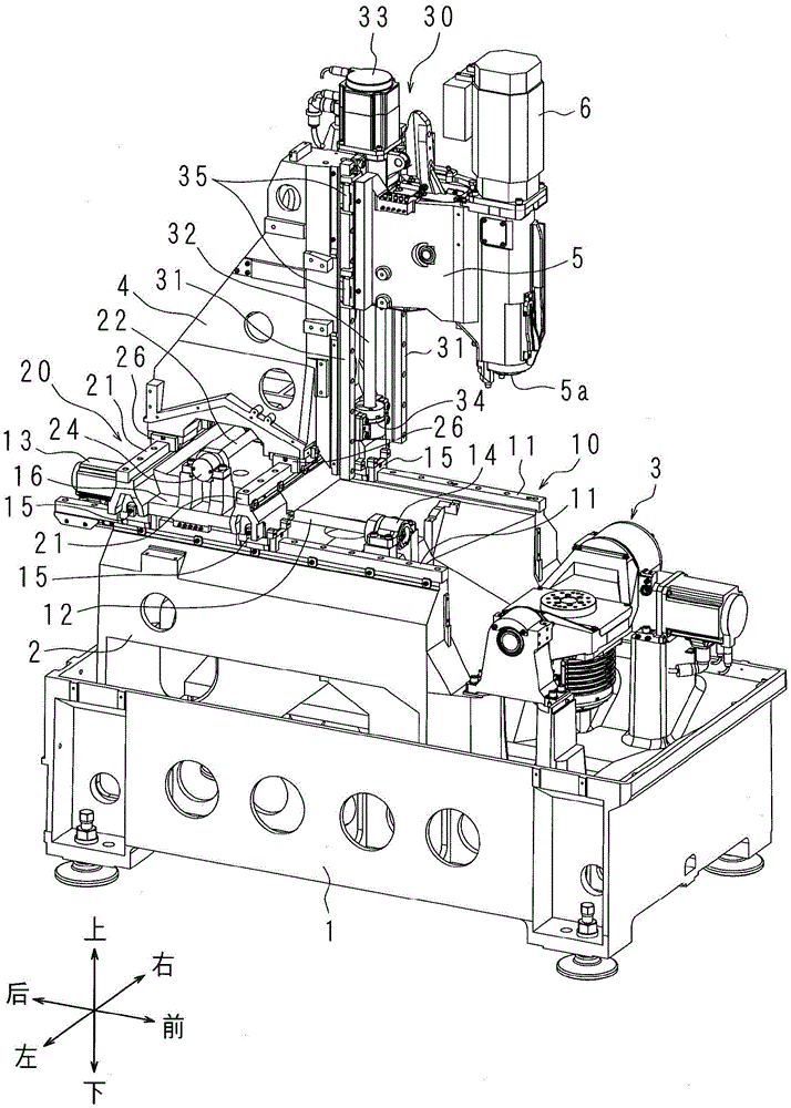
[0024] Next, a machine tool according to an embodiment of the present invention will be described with reference to the drawings. Front and rear, left and right, up and down of the machine tool figure 1 indicated by the arrow in .

[0025] The machine tool has a rectangular base 1 extending in the front-rear direction. The workpiece holding part 3 is provided on the upper front side of the base 1 . The workpiece holding part 3 is rotatable around the A axis and the C axis. The A-axis takes the left-right direction as the axial direction, and the C-axis takes the vertical direction as the axial direction.

[0026] The support stand 2 supporting the upright column 4 is provided on the upper part of the base 1 near the rear side. The Y-axis direction movement mechanism 10 is provided on the upper part of the support table 2 . The Y-axis direction moving mechanism 10 can move the moving plate 16 in the front-rear direction. The Y-axis direction moving mechanism 10 has a Y-ax...


PUM


Abstract

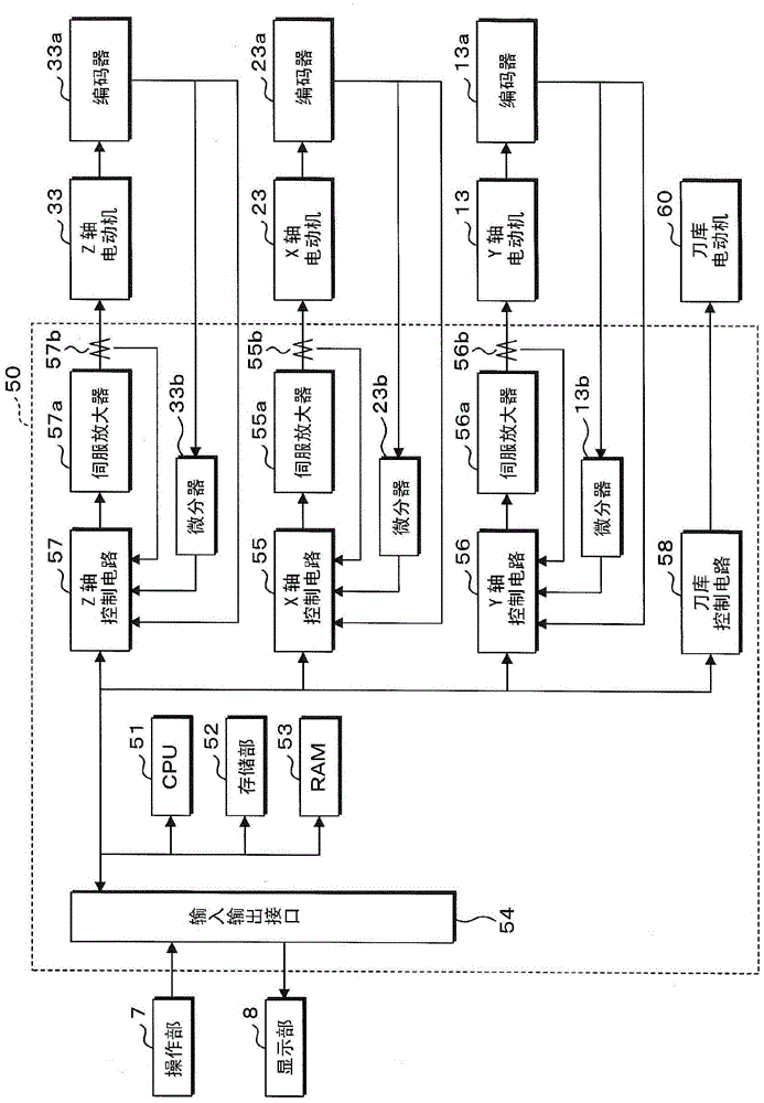
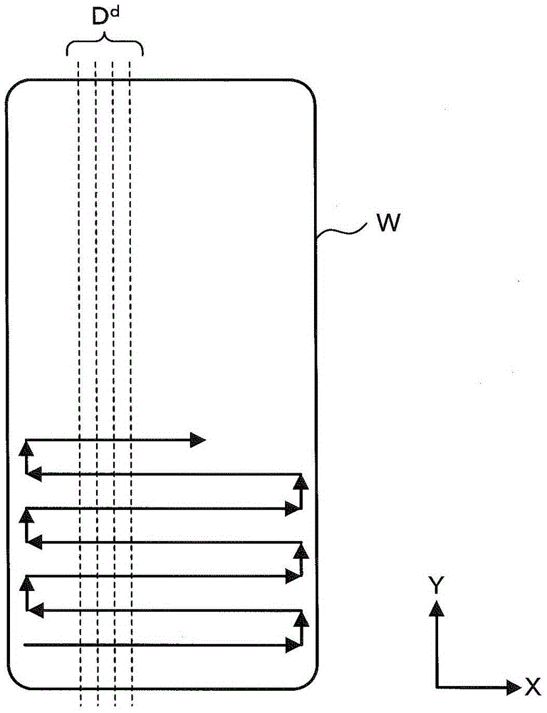
The invention provides a control device, a machine tool and a control method. The control device is capable of controlling a main shaft for the assembling of a tool to move or a workpiece holding part for holding a workpiece to move. The control device sets a machining path based on instruction points of positions of a plurality of indication shafts and further control the main shaft to move based on the machining path. The control device sets an evaluation section crossed with the machining path and then carries out operation to obtain the intersection point between the set evaluation section and the machining path. The position of the intersection point is corrected, and the positions of the instruction points in the direction crossed with the machining path are corrected based on the corrected intersection point. The control device is capalbe of correcting the instruction position in the direction crossed with the machining path, so that a smooth curved surface is formed on the workpiece.

Description

technical field [0001] The present invention relates to a control device, a machine tool and a control method capable of controlling the movement of a spindle on which a tool is assembled or a workpiece holding portion for holding a workpiece. Background technique [0002] The machine tool has a spindle and controls. The control device controls the movement of the spindle, which is used for tool assembly. The control device sets a plurality of instruction points indicating the position of the spindle, and further sets the machining path. When the tool assembled on the spindle is to form a three-dimensional curved surface on the workpiece, the control device performs calculations to generate a plurality of curves. The curve is formed by continuous small line segments between command points. [0003] Japanese Registered Patent Publication No. 3466111 discloses a control device. The control device generates, for example, a plurality of curves on a horizontal plane. Multipl...

Claims


Application Information

Patent Timeline
Patent Type & Authority Applications(China)
IPC IPC(8): G05B19/414
CPCG05B19/4141G05B2219/35097
Inventor 石川友哉西田晋
Owner BROTHER KOGYO KK
Learn More