
Wavelength correction control system for dye laser

A dye laser and control system technology, applied in the field of dye laser wavelength correction control system, can solve the problems of laser wavelength stability not reaching stability, and achieve the effect of realizing intelligence and strong pertinence

Active Publication Date: 2016-10-12
HEFEI INSTITUTES OF PHYSICAL SCIENCE - CHINESE ACAD OF SCI
View PDF6 Cites 4 Cited by
  • Summary
  • Abstract
  • Description
  • Claims
  • Application Information

AI Technical Summary

Problems solved by technology

However, the stability of the laser wavelength itself is often not up to the stability required for monitoring

Method used


Image

  • Wavelength correction control system for dye laser
  • Wavelength correction control system for dye laser

Examples


Embodiment Construction

[0032] The following will clearly and completely describe the technical solutions in the embodiments of the present invention with reference to the accompanying drawings in the embodiments of the present invention. Obviously, the described embodiments are only some, not all, embodiments of the present invention. Based on the embodiments of the present invention, all other embodiments obtained by persons of ordinary skill in the art without making creative efforts belong to the protection scope of the present invention.

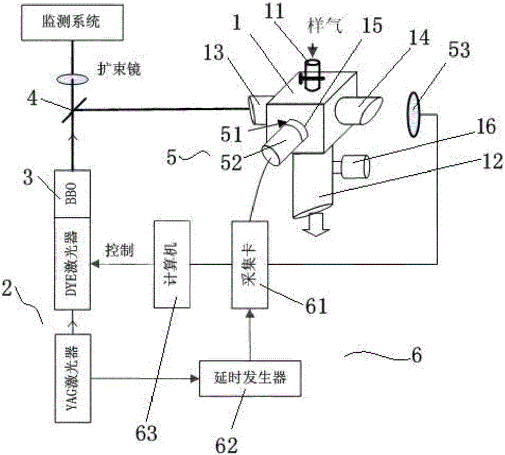
[0033] The invention provides a wavelength correction control system for a dye laser, comprising:

[0034] The sample cell 1, the sample cell 1 includes an air inlet 11 located at the top of the sample cell 1, a vacuum port 12 located at the bottom of the sample cell 1, and an incident window 13 and an exit window 14 symmetrically arranged on both sides of the sample cell 1, vertically The signal collection port 15 located on the other side of the sample cell ...


PUM


Abstract

The invention provides a wavelength correction control system for a dye laser. The system comprises the dye laser, a sample pool, a signal detection unit and a signal processing unit, wherein laser emitted by the dye laser is subjected to frequency multiplication by a beta-Ba2O4 crystal and then output, the laser output after frequency multiplication is split by a beam splitter and then enters the sample pool through an entrance window; the signal detection unit comprises a fluorescence collection lens of a narrowband filter and is used for filtering interference and focusing a fluorescence signal excited by laser, the fluorescence signal is acquired by a photomultiplier, and a laser energy signal is monitored by a photodiode. A signal acquisition card of the signal processing unit receives the signals acquired by the photomultiplier and the photodiode and transmits the signals to a computer, and the computer controls gratings of the dye laser and parameters of the beta-Ba2O4 crystal through a USB, so that the laser output wavelength is regulated. With the adoption of the wavelength correction control system, the wavelength of the dye laser on a to-be-detected substance excitation line can be accurately located, and the location precision is as high as 0.1 pm.

Description

technical field [0001] The invention relates to the technical field of atmospheric trace gas monitoring with relatively strong selective absorption and relatively narrow absorption line width in environmental monitoring. In particular, it relates to a wavelength correction control system for dye lasers. Background technique [0002] With the rapid development of the economy, environmental problems are becoming more and more serious, especially the problem of air pollution is getting more and more attention. The composition and concentration of polluting gases in the atmosphere are the primary concern in the control of air pollution. However, there are still many problems in the monitoring of trace gases with relatively strong activity and relatively low concentration in the atmosphere. Especially when laser-induced fluorescence technology is used to detect the concentration of the analyte, the laser excites the analyte to produce fluorescence, and the concentration of the ...

Claims


Application Information

Patent Timeline
IPC IPC(8): G01N21/64
CPCG01N21/6402
Inventor 胡仁志杏兴彪谢品华陈浩凌六一刘建国刘文清
Owner HEFEI INSTITUTES OF PHYSICAL SCIENCE - CHINESE ACAD OF SCI
Learn More