
A system for improving the zero-bias performance of silicon microgyroscopes packaged at atmospheric pressure

A silicon micro-gyroscope and zero bias technology, applied in steering sensing equipment and other directions, can solve the problems that the quality factor cannot tend to 0, the trouble of extracting the vibration amplitude of the detection direction, and the impact of zero bias performance, etc., to achieve low power consumption and low cost , Improve the effect of zero bias performance

Active Publication Date: 2018-09-21
SOUTHEAST UNIV
View PDF6 Cites 0 Cited by
  • Summary
  • Abstract
  • Description
  • Claims
  • Application Information

AI Technical Summary

Problems solved by technology

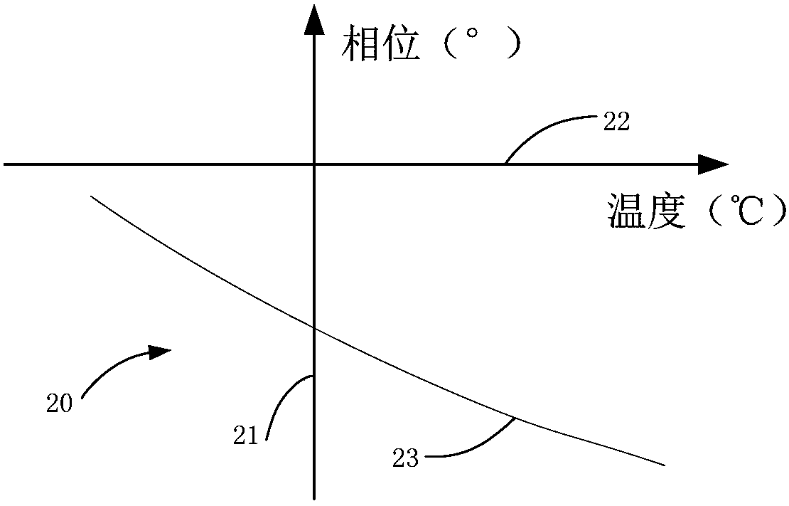
[0007] Since the quality factor of the atmospheric pressure packaged silicon micro gyroscope is relatively small, the quality factor cannot tend to 0, which will bring some trouble to the extraction of the vibration amplitude of the detection direction. At the same time, because the quality factor changes with the change of temperature, in During the whole temperature process, the quality factor changes all the time, which will also have a great impact on the zero bias performance

Method used


Image

  • A system for improving the zero-bias performance of silicon microgyroscopes packaged at atmospheric pressure
  • A system for improving the zero-bias performance of silicon microgyroscopes packaged at atmospheric pressure
  • A system for improving the zero-bias performance of silicon microgyroscopes packaged at atmospheric pressure

Examples


Embodiment Construction

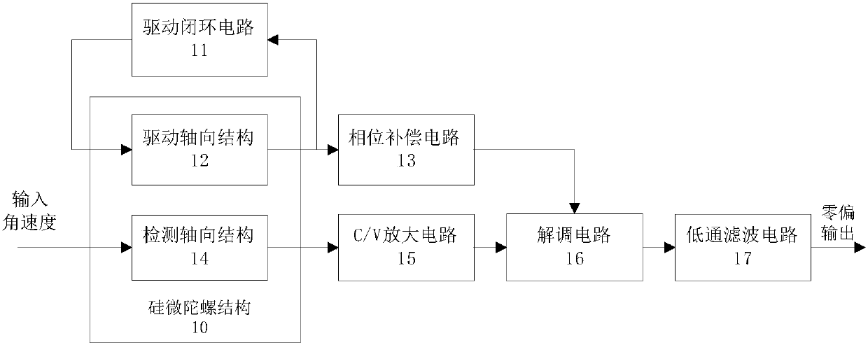
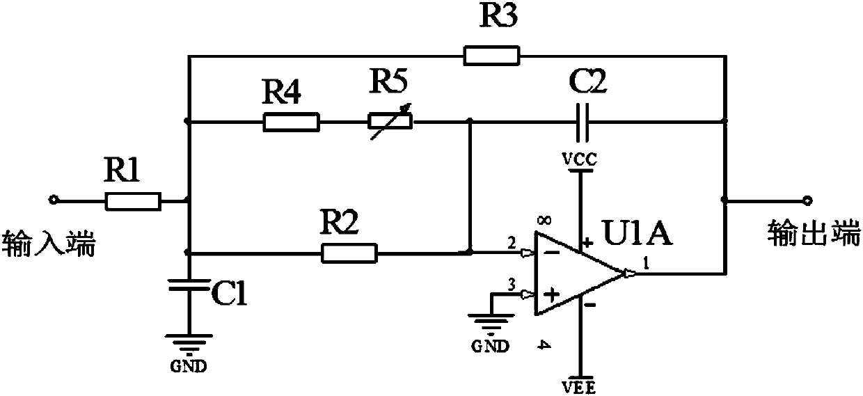
[0035] see figure 1 , the present invention provides a schematic diagram of an open-loop detection circuit of an atmospheric pressure packaged gyroscope. The atmospheric pressure packaged silicon microgyro structure 10 includes a driving axial structure 12 and a detecting axial structure 14. The driving axial structure 12 Form the driving closed-loop circuit with the driving closed-loop circuit 11, ensure that the equivalent mass of the driving mode vibrates along the X-axis direction with constant amplitude and constant frequency; the open-loop detection circuit includes a C / V amplifier circuit 15, a phase compensation circuit 13, demodulation circuit 16 and low pass filter 17. The C / V amplifying circuit 15 is used to convert the capacitance change amount of the detection mode into a voltage signal and amplify it. The phase compensation circuit 13 is used to compensate Q y The additional phase generated by the value becomes smaller, so that the signal to be demodulated and ...


PUM


Abstract

The invention discloses a system for improving the zero bias performance of a normal pressure packaged silicon micro-gyroscope. The system includes a silicon micro-gyroscope structure, a closed-loop driving circuit and an open-loop detection circuit, and the silicon micro-gyroscope structure includes a driving axial structure and a detection axial structure; the driving axial structure and the closed-loop driving circuit form a closed-loop driving loop, and the closed-loop driving loop is used for guaranteeing constant-amplitude and constant-frequency vibration of the equivalent quality of driving modulus along an X-axial direction; the detection axial structure is sequentially connected with a capacitance-voltage conversion amplifier circuit, a switching demodulation circuit and a low-pass filter, the driving axial structure is connected to the switching demodulation circuit through a phase compensation circuit, and the driving axial structure is connected with the closed-loop driving circuit in parallel; and the open-loop detection circuit includes a capacitance-voltage conversion amplifier circuit, a phase compensation circuit, a switching demodulation circuit and a low pass filter.

Description

technical field [0001] The invention relates to the field of silicon microgyroscopes packaged at normal pressure, in particular to a system for improving the zero bias performance of silicon microgyroscopes packaged at normal pressure. Background technique [0002] Micromechanical gyroscopes have not only been widely used in the fields of military industry and weaponry, but also have considerable prospects in vehicle-mounted systems, mobile phone communications, and civilian navigation. Since vacuum packaging technology is an important way to improve the performance of micro-machined gyroscopes, at present, most of the production of micro-machined gyroscopes uses vacuum packaging, which also greatly increases its production cost. In order to save costs and achieve mass production, packaging gyroscopes under atmospheric pressure has gradually attracted attention. Although the atmospheric pressure packaging technology will reduce the quality factor of the system and reduce th...

Claims


Application Information

Patent Timeline
Patent Type & Authority Patents(China)
IPC IPC(8): G01C19/56
CPCG01C19/56
Inventor 李宏生桑鹏程丁徐锴黄丽斌张婷
Owner SOUTHEAST UNIV
Learn More