
Structural light measurement sensor calibration method

A technology for measuring sensors and calibration methods, used in measuring devices, instruments, using optical devices, etc.

Inactive Publication Date: 2016-10-12
HENAN ALSONTECH INTELLIGENT TECH CO LTD
View PDF7 Cites 10 Cited by
  • Summary
  • Abstract
  • Description
  • Claims
  • Application Information

AI Technical Summary

Problems solved by technology

[0004] The ultimate purpose of the present invention is to provide a new calibration method for structured light measurement sensors, by directly calculating the three-dimensional points on the structured light surface, and then calculating the parameters of the structured light surface equation, which overcomes the need for a common calibration method in the existing calibration methods. face reference target

Method used


Image

  • Structural light measurement sensor calibration method
  • Structural light measurement sensor calibration method
  • Structural light measurement sensor calibration method

Examples


Embodiment Construction

[0038] In order to further explain the technical means and effects adopted by the present invention to achieve the intended purpose of the invention, the specific implementation, method, Steps, features and effects thereof are described in detail below.

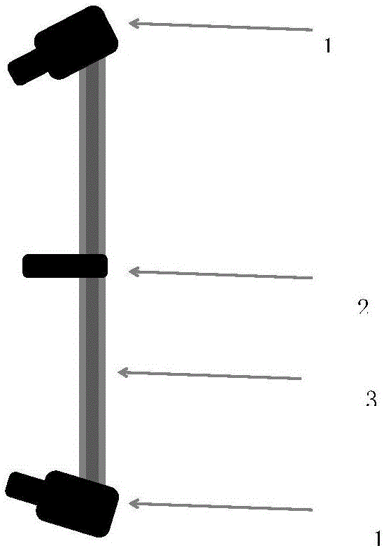
[0039] see Figure 1-4 A method for calibrating a structured light measurement sensor of the present invention comprises the following steps:

[0040] The first step is to place the target in front of the laser 2 to ensure that the laser can be projected onto the target. The two oriented cameras 1 are placed on the upper and lower parts of the laser 2 respectively, so that they can capture the laser light on the target. spot.

[0041] The second step is to control the upper and lower cameras 1 to capture target images synchronously to obtain images L1 and L2.

[0042] The third step is to process the images L1 and L2 respectively, and extract the center coordinates of the light spot on the image. The specific processing s...


PUM


Abstract

Provided is a structural light measurement sensor calibration method. The method comprises the following steps that 1, a target is put in front of a laser, laser light is projected to the target, two cameras are put on the upper portion and lower portion of the laser respectively, and laser light spots of the target can be shot; 2, the upper camera and the lower camera are controlled to synchronously shoot target images, and an image L1 and an image L2 are obtained; 3, the image L1 and the image L2 are processed respectively, and central coordinates of the light spots on the images are extracted; 4, image points are matched by means of epipolar rays for epipolar ray matching; 5, three dimensional point coordinates of points on the laser light surface are calculated; 6, the position of the target is changed, and the steps from first to fifth are repeated more than once; 7, a laser light equation is fitted through three-dimensional points. According to the structural light measurement sensor calibration method, the calibration difficulty is reduced, and application and popularization of the structural light measurement method are promoted; a simpler measuring tool is provided for social production, the production efficiency is improved, and social wealth is created.

Description

technical field [0001] The invention relates to the field of sensor device parameter calibration, in particular to a structured light measurement sensor calibration method. Background technique [0002] The existing structured laser calibration methods have problems such as cumbersome process, the need for coplanar reference targets, and the need to calculate laser plane parameters through coplanar targets. [0003] In view of the defects in the above-mentioned existing structured cursor calibration method, the inventor actively researches and innovates based on years of rich practical experience and professional knowledge in the design and manufacture of this type of product, and cooperates with the application of academic theories, in order to create a new one. The calibration method of structured light measurement sensor can improve the general existing structured light calibration method and make it more practical. Through continuous research, design, and after repeated...

Claims


Application Information

Patent Timeline
IPC IPC(8): G01B11/00
CPCG01B11/002
Inventor 崔庆张卓辉王志飞向宇李晓亮夏璐璐高梓翔
Owner HENAN ALSONTECH INTELLIGENT TECH CO LTD
Learn More