Equipment and method for improving sliver quality by double row reciprocating electrospinning
An electrospinning method and electrospinning technology are applied in the field of providing a low-cost, textile equipment, and high-efficiency improvement of sliver quality, which can solve the problems of electrostatic phenomenon affecting the quality of sliver, and achieve the solution of electrostatic phenomenon and environmental protection. Strong performance and good antistatic effect
- Summary
- Abstract
- Description
- Claims
- Application Information
AI Technical Summary
Problems solved by technology
Method used
Image
Examples
Embodiment 1
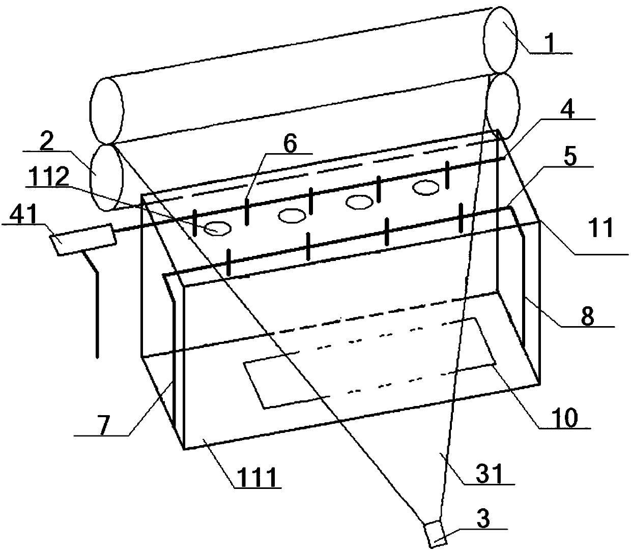
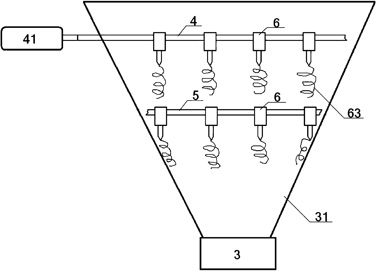
[0071] see figure 1 - Figure 7 , a device for improving the quality of raw sliver by double-row reciprocating electrospinning method, comprising an upper roll 1, a lower roll 2, a bell mouth 3 and a cotton net 31, and the upper roll 1 and the lower roll 2 are arranged in parallel up and down One side of the cotton web 31 penetrates from the gap before the upper roll 1 and the lower roll 2, and the other side of the cotton web 31 passes through the bell mouth 3, and the cotton web 31 is located between the upper roll 1, the lower roll 2 and the horn. The part between mouth 3 exists in a triangular shape;
[0072] The bottom of the cotton net 31 is provided with a grounded metal pole plate 10 (which can be connected to the machine frame of the carding machine), and the top of the cotton net 31 is suspended with parallel horizontal reciprocating rods 4, horizontal fixed rods 5, and horizontal reciprocating rods. 4. The horizontal fixed rod 5 is parallel to the upper roll 1 and...
Embodiment 2
[0076] Basic content is the same as embodiment 1, the difference is:
[0077] The middle part of the transverse reciprocating rod 4 is located directly above the cotton web 31, and the left end of the transverse reciprocating rod 4 extends to the outside of the cotton web 31. The middle part of the transverse reciprocating rod 4 is provided with a plurality of electrospinning nozzles 6. The left end of rod 4 is connected with the output shaft of reciprocating cylinder 41, and the bottom of reciprocating cylinder 41 is connected with No. 1 vertical adjustment device 7 or the top of No. 2 vertical adjustment device 8. No. 1 vertical adjustment device 7, No. 2 vertical adjustment device The bottom of the vertical adjustment device 8 is respectively provided with a longitudinal moving device 9; the middle part of the horizontal fixing rod 5 is positioned directly above the cotton net 31, and the two ends of the horizontal fixing rod 5 then extend to the outside of the cotton net 31...
Embodiment 3
[0081] Basic content is the same as embodiment 2, the difference is:
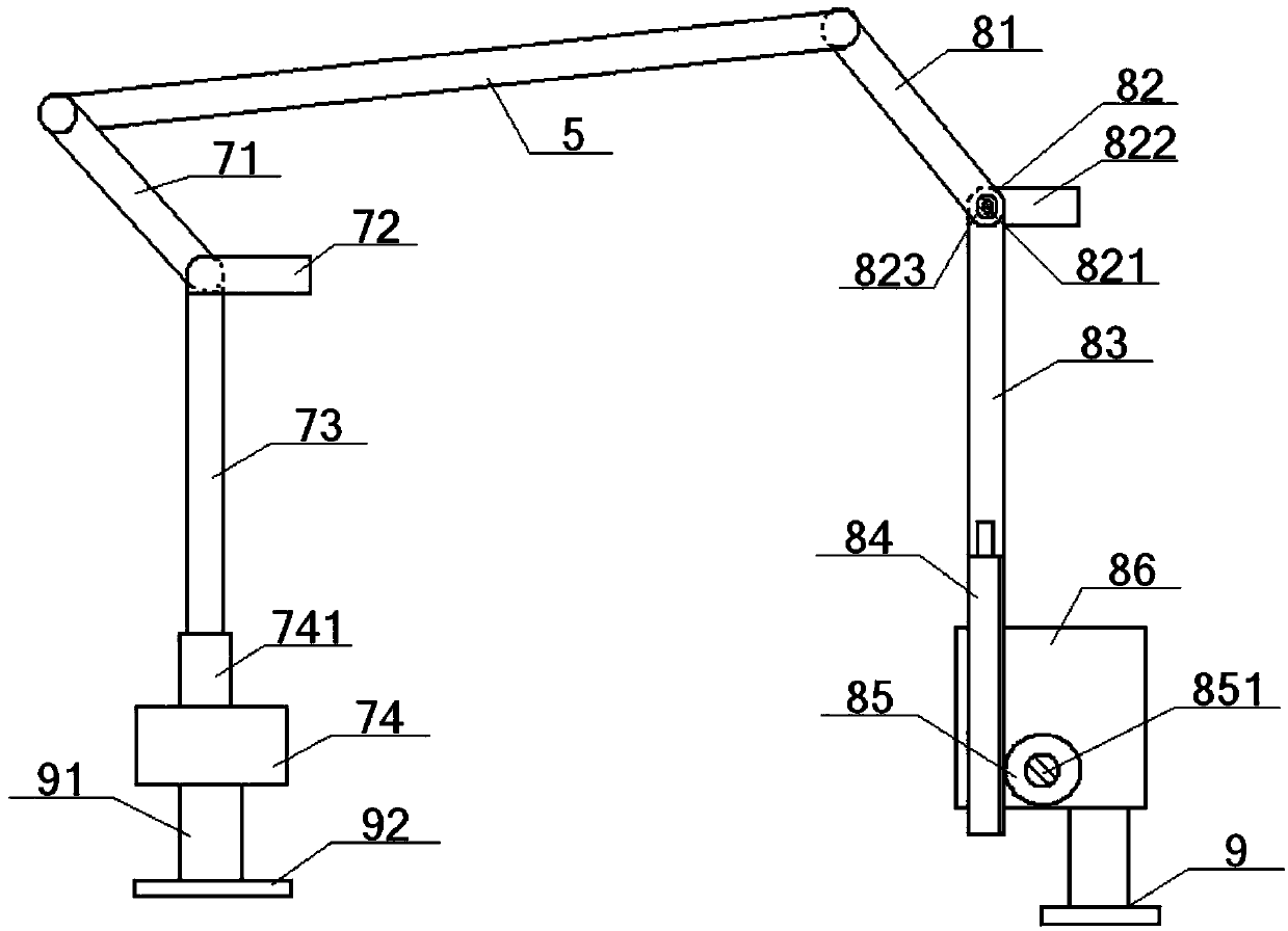
[0082]The No. 1 vertical adjustment device 7 includes a No. 1 swing arm 71, a No. 1 handle 72, a No. 1 vertical rod 73 and a No. 1 cylinder 74. The top of the No. 1 swing arm 71 is connected to the left end or reciprocating The bottom of the cylinder 41 is connected, the bottom of the No. 1 swing arm 71 is hinged with the top of the No. 1 vertical rod 73, and the bottom of the No. 1 vertical rod 73 is connected with the driving rod 741 arranged on the top of the No. 1 cylinder 74. The bottom of the No. 1 cylinder 74 is connected with the longitudinal moving device 9; the No. 1 handle 72 is an L-shaped structure, including a No. 1 connecting shaft 721 and a No. 1 drive plate 722 vertically connected to each other, and the inner end of the No. 1 drive plate 722 It is connected with the outer end of the No. 1 connecting shaft 721 , and the inner end of the No. 1 connecting shaft 721 passes through the junction...
PUM
 Abstract
Description
Claims
Application Information
 - R&D
- Intellectual Property
- Life Sciences
- Materials
- Tech Scout
- Unparalleled Data Quality
- Higher Quality Content
- 60% Fewer Hallucinations
Browse by: Latest US Patents, China's latest patents, Technical Efficacy Thesaurus, Application Domain, Technology Topic, Popular Technical Reports.
© 2025 PatSnap. All rights reserved.Legal|Privacy policy|Modern Slavery Act Transparency Statement|Sitemap|About US| Contact US: help@patsnap.com


