Forward osmosis membrane and MF (microfiltration) membrane coupling anaerobic sewage treatment method

A technology of forward osmosis membrane and microfiltration membrane, which is applied in the field of sewage treatment, can solve problems such as limiting the application of reactors, and achieve the effect of recycling resources

Inactive Publication Date: 2016-10-12
JIANGNAN UNIV
View PDF10 Cites 4 Cited by
  • Summary
  • Abstract
  • Description
  • Claims
  • Application Information

AI Technical Summary

Problems solved by technology

The accumulation of salinity greatly limits the further application of the reactor
Currently, no solutions for high salinity in AnFOMBR have been reported

Method used


Image

  • Forward osmosis membrane and MF (microfiltration) membrane coupling anaerobic sewage treatment method

Examples


Embodiment 1

[0037] Embodiment 1: anaerobic reactor coupling forward osmosis membrane and microfiltration membrane

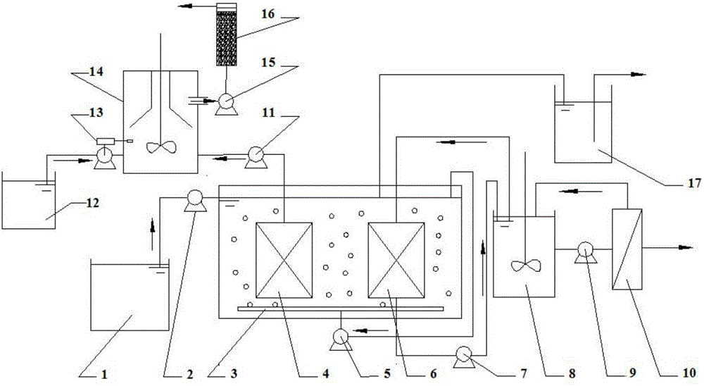
[0038] figure 1 It is a structural schematic diagram of an anaerobic reactor (MFO-AnMBR) coupled with a forward osmosis membrane and a microfiltration membrane of the present invention.

[0039]The anaerobic reactor mainly includes a membrane reaction device, a draw liquid pool 8, a RO membrane treatment device 10, a sedimentation tank 14, and an adsorption device 16; the membrane reaction device includes a MF membrane module 4 and a FO membrane module 6; the MF The membrane module 4 is connected with the sedimentation tank 14 through the pipeline, and the sedimentation tank 14 is connected with the adsorption device 16 through the pipeline; the FO membrane module 6 is connected with the draw liquid pool 8 through the pipeline, and the draw liquid pool 8 is connected with the RO membrane treatment device 10 connect.

[0040] An aeration pipe 3 is installed at the bottom of...

Embodiment 2

[0049] Embodiment 2: utilize MFO-AnMBR of the present invention to carry out sewage treatment

[0050] use as figure 1 A novel anaerobic reactor (MFO-AnMBR) coupled with forward osmosis membrane and microfiltration membrane with the structure shown, operates at room temperature.

[0051] The artificially prepared simulated urban sewage is introduced, and its water quality index is: TOC: 143.97±2.23mg / L, NH 4 -N: 28.95±2.34mg / L, TN: 30.71±2.18mg / L, TP: 2.70±0.34mg / L. FO and MF flat membrane modules are used for membrane modules, which are made of triacetate fiber (CTA) and polyvinylidene fluoride (PVDF) respectively, and the membrane area is 0.025m 2 , where the average pore size of MF is 0.2 μm. The water inlet pump 2 pumps the water from the water inlet tank 1 into the MFO-AnMBR, and is rapidly mixed under the action of the biogas circulation pump 5 . A part of the mixed liquid passes through the FO membrane module 6 under the action of the drawing liquid 8 to realize the...


PUM

PropertyMeasurementUnit
areaaaaaaaaaaa
pore sizeaaaaaaaaaa

Abstract

The invention discloses a forward osmosis membrane and MF (microfiltration) membrane coupling anaerobic sewage treatment method, and belongs to the technical field of sewage treatment. For municipal sewage, the method comprises the following steps: causing raw water to enter an anaerobic reaction area through a water feed pump, and collecting generated biogas for reuse after the biogas passes through a water seal; for part of sewage, implementing separation and purification under the action of a forward osmosis membrane, and then implementing reuse by treatment with a reverse osmosis membrane; for the other part of sewage, implementing separation and purification by virtue of an MF membrane, then recycling phosphate by virtue of a sedimentation tank, and finally implementing up-to-standard effluent discharge or reuse by virtue of an activated carbon adsorption column. According to the method, forward osmosis membrane and MF membrane technologies and an anaerobic digestion technology are coupled into a sewage treatment process, so that effluent is guaranteed to stably meet reclaimed water reuse requirements, and a smaller area is occupied; organic matters in the sewage are recycled in form of biogas; the phosphate in the sewage is recycled; salinity accumulation of forward osmosis is relieved, and membrane pollution is effectively controlled; the whole system can be automatically controlled.

Description

technical field [0001] The invention relates to an anaerobic sewage treatment method coupled with a forward osmosis membrane and a microfiltration membrane, belonging to the technical field of sewage treatment. Background technique [0002] A large amount of sewage discharge not only wastes resources, but also increases the environmental load of water bodies. With the increasing shortage of water resources and energy in the world, sewage has been regarded as a water source and resource due to its rich water resources and a large amount of C, N, P and other resources. In this context, the sewage treatment process for the purpose of sewage reuse and energy recovery has received more and more attention. Anaerobic membrane bioreactor (AnMBR) is such a process, which can recover methane in the process of sewage treatment, and the introduction of microfiltration or ultrafiltration membrane separation technology has greatly improved the effect of anaerobic effluent. However, AnMB...

Claims


Application Information

Patent Timeline
Patent Type & Authority Applications(China)
IPC IPC(8): C02F9/14C02F101/30C02F101/16
CPCC02F9/00C02F2301/046C02F2303/14C02F2209/06C02F2209/05C02F2209/08C02F2101/16C02F2101/30C02F2101/105C02F3/2853C02F3/2893C02F1/66C02F1/52C02F1/445C02F1/444C02F1/441C02F1/281C02F1/283B01D61/58B01D61/002B01D61/025B01D2311/2688B01D2311/08B01D61/0023
Inventor 王新华王臣胡涛战李秀芬
Owner JIANGNAN UNIV
Why Eureka
Try Eureka