
Short-screw double material extruding machine

An extruder and screw technology, which is applied in the field of short-screw twin-material extruders, can solve the problems of insufficient extruder capacity and shortened delivery cycle, and achieve the effect of low replacement and maintenance cost and shortened length.

Inactive Publication Date: 2016-10-12
无锡久耐聚氨酯制品有限公司
View PDF8 Cites 2 Cited by
  • Summary
  • Abstract
  • Description
  • Claims
  • Application Information

AI Technical Summary

Problems solved by technology

[0003] If the existing screw extruder wants to obtain good quality injection molding products, the screw must be long enough so that it has enough mixing length to fully melt the thermoplastic resin material. Therefore, the extruder tends to be larger
In recent years, the delivery cycle of products has been shortened, and the plasticizing speed of the screw is required to be faster and faster, and many extruders have become unable to do what they want.

Method used


Image

  • Short-screw double material extruding machine
  • Short-screw double material extruding machine

Examples


Embodiment 1

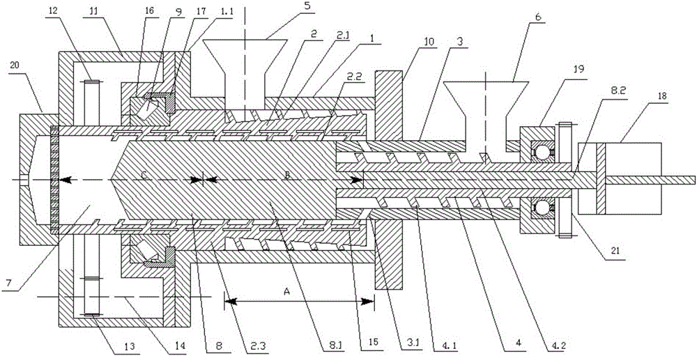
[0033] As shown in the figure, a short-screw double-material extruder includes a first barrel 1 and a first screw 2, the first screw 2 is rotatably arranged in the first barrel 1, and the first screw 2 includes a central through-hole Screw body, the screw body has a left support part 2.3, the outer cylinder of the first screw rod 2 is provided with a first outer screw edge 2.1 between the left support part 2.3 and the right end, in the center hole from the corresponding inner hole of the right end There is a first internal thread 2.2 from the position, and the injection shaft 8 fits in the first internal thread 2.2;

[0034] As shown in the figure, the helical directions of the first outer flight 2.1 and the first inner flight 2.2 are set in opposite directions, when the first outer flight 2.1 is a right-handed flight, the first inner flight 2.2 is a left-handed flight, so Only in this way can it be ensured that when the first screw 2 rotates counterclockwise, the conveying di...

Embodiment 2

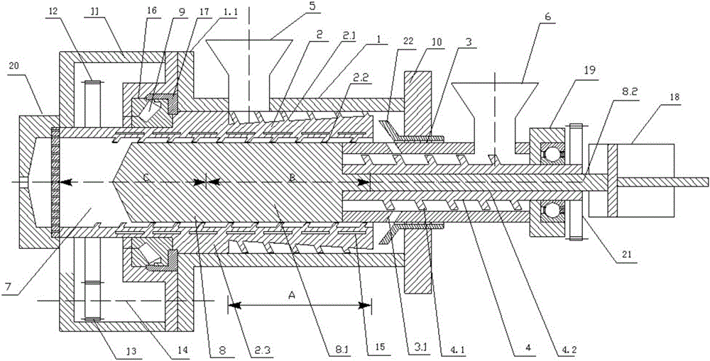
[0045] The right end of the screw body of the first screw 2, the first right baffle plate 10 and the annular inlet channel between the right end center through hole of the screw body of the first screw and the second barrel 3 constitute a mixing section, and the discharge ramp The outlet of the hole 3.1 is located in the mixing section, and a mixing impeller 22 is rotated in the mixing section, and the mixing impeller 22 mixes the materials in the screw conveying section A and the screw conveying section D. The mixing impeller 22 is rotatably arranged in the first right baffle plate 10, and the mixing impeller 22 is driven by a separate rotary driving device. The mixing impeller 22 fully mixes the materials in the mixing screw conveying section A and the screw conveying section D, and then enters the inner screw plasticizing section B from the annular inlet. The blade profile of the mixing impeller 22 is conical, and the large end of the conical ring is facing the annular chan...


PUM


Abstract

The invention relates to a short-screw double material extruding machine which comprises a first machine barrel (1), a first screw (2), a second machine barrel (3), a second screw (4) and an injection shaft (8), wherein the first screw (2) comprises left support parts (2, 3), a first external screw flight (2.1) is arranged outside the screw body, a first internal screw flight (2.2) is arranged at the center hole of the screw body, the second screw (4) is rotatably arranged in the second machine barrel (3); the second screw (4) comprises a screw body with a center through hole (4.2), the screw body has a second external screw flight (4.1), and a discharge inclined hole (3.1) is formed in the outer peripheral wall of the left end of the second machine barrel; and the injection shaft (8) comprises an injection shaft body part (8.1) and a connecting rod part (8.2) which are connected end to end, and the connecting rod part (8.2) passes through the center through hole (4.2) of the second screw (4) to be connected with a driving device (18). According to the short-screw double material extruding machine, on the premise of not increasing the length of the screw, a small extruding machine with double material input is designed, and the plastifying efficiency is improved.

Description

technical field [0001] The invention relates to the technical field of extruders, in particular to a short-screw double-material extruder. Background technique [0002] Screw extruder is an important equipment for plastic processing, and the screw is its core component. The length of the screw determines the length of the extruder. In the extruder, the barrel / screw has three functions: one is the feeding and conveying function, that is, the feeding section; the other is the plasticizing function, which melts the pellets into a plastic melt, that is, the plasticizing section; the third is stable extrusion The extrusion section must have a melt metering effect. [0003] If the existing screw extruder wants to obtain good-quality injection molding products, the screw must be long enough so that it has enough mixing length to fully melt the thermoplastic resin material. Therefore, the extruder tends to be larger. In recent years, the delivery cycle of products has been shorten...

Claims


Application Information

Patent Timeline
Patent Type & Authority Applications(China)
IPC IPC(8): B29C47/48B29C47/60B29C48/445
CPCB29C48/445B29C48/505
Inventor 高飞夏文胜张文明
Owner 无锡久耐聚氨酯制品有限公司
Learn More