Measuring method of measuring device for machining error of thin-walled parts based on spatial light modulator

A spatial light modulator and thin-walled parts processing technology, which is applied in the optical field, can solve the problems of thin-walled surface deformation due to force, inapplicability of online detection, slow measurement speed, etc., to achieve accurate measurement, save measurement space, and save measurement the effect of the space

Inactive Publication Date: 2018-09-25
HARBIN UNIV OF SCI & TECH
View PDF8 Cites 0 Cited by
  • Summary
  • Abstract
  • Description
  • Claims
  • Application Information

AI Technical Summary

Problems solved by technology

[0002] At present, the surface machining error measurement of the thin-walled curved surface (impeller blade) in CNC machining usually adopts contact measurement. During the measurement, because it moves on the surface of the thin-walled curved surface (impeller blade), the measurement speed is slow. On the one hand, it is difficult to measure less than the measurement The error of the microscopic pit of the head curvature radius, on the other hand, easily deforms the surface of the thin-walled curved surface under force, so it cannot be applied to real-time online detection;

Method used


Image

  • Measuring method of measuring device for machining error of thin-walled parts based on spatial light modulator
  • Measuring method of measuring device for machining error of thin-walled parts based on spatial light modulator
  • Measuring method of measuring device for machining error of thin-walled parts based on spatial light modulator

Examples


Embodiment 1

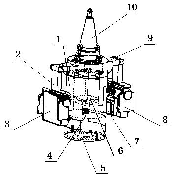
[0036] A processing error measurement device for thin-walled parts based on a spatial light modulator, which consists of: a set of measurement devices 14, the measurement device includes a sleeve 1, and the upper part of the sleeve is connected to the support device 9 by bolts, Both ends of the support device are respectively connected to two modulator card clamping devices 2 through connecting shafts, and the left liquid crystal spatial light modulator 3 and the right liquid crystal spatial light modulator are respectively installed inside the modulator card clamping device. 8. The inner surfaces of the left liquid crystal spatial light modulator and the right liquid crystal spatial light modulator are respectively equipped with polarizers 7, and a digital phase shift interferometer 6 is installed above the sleeve through a square groove.

Embodiment 2

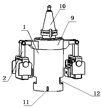
[0038] According to the processing error measurement device for thin-walled parts based on the spatial light modulator described in Embodiment 1, the lens sleeve device 4 is installed under the digital phase-shift interferometer, and the zero position compensation is installed under the inside of the sleeve. The lens device 5 has two protruding blocks on the outside of the zero compensation lens device, and the protruding blocks are installed in the track groove outside the sleeve, and the track device 11 is installed in the track groove , the outer side of the sleeve has two viewing windows 12

Embodiment 3

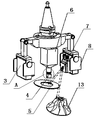
[0040] According to the processing error measuring device for thin-walled parts based on the spatial light modulator described in Embodiment 1, the upper part of the supporting device is connected to the handle 10 by bolts, and the thin-walled part to be measured is placed in the middle of the group of measuring devices. Workpiece 13.


PUM


Abstract

The invention relates to a thin-wall part machining error measuring device and a thin-wall part machining error measurement method based on a spatial light modulator. The surface error measurement of a machined thin-wall part is contact measurement generally; during the measurement, the surface of the part is in contact with the measuring device, and the movement speed during the measurement is relatively low, so a microcosmic pit which has smaller curvature radius than a measuring head cannot be measured. The thin-wall part machining error measuring device disclosed by the invention comprises a group of measuring devices (14); each measuring device comprises a sleeve (1); the upper part of each sleeve is connected with a supporting device (9) through a bolt; the two ends of each supporting device are respectively connected with two modulator clamping devices (2) through connecting shafts; a left liquid crystal spatial light modulator (3) and a right liquid crystal spatial light modulator (8) are respectively mounted inside the modulator clamping devices; polarizing films (7) are separately mounted at the inner surfaces of the left liquid crystal spatial light modulator (3) and the right liquid crystal spatial light modulator (8); a digital phase-shift interferometer (6) is mounted at the upper portion of the corresponding sleeve through a square groove. The measurement method disclosed by the invention is applied to the thin-wall part machining error measuring device based on the spatial light modulator.

Description

Technical field: [0001] The invention relates to the field of optics, in particular to a device and method for measuring machining errors in machined surfaces and measuring the surface quality of thin-walled parts. Background technique: [0002] At present, the surface machining error measurement of the thin-walled curved surface (impeller blade) in CNC machining usually adopts contact measurement. During the measurement, because it moves on the surface of the thin-walled curved surface (impeller blade), the measurement speed is slow. On the one hand, it is difficult to measure less than the measurement The error of the microscopic pit of the head curvature radius, on the other hand, easily deforms the surface of the thin-walled curved surface under force, so it cannot be applied to real-time online detection; [0003] The device adopts non-contact measurement to measure the thin-walled curved surface on the premise of not touching the measured thin-walled parts, which can p...

Claims


Application Information

Patent Timeline
Patent Type & Authority Patents(China)
IPC IPC(8): B23Q17/20B23Q17/24
CPCB23Q17/20B23Q17/2471
Inventor 吴石王洋洋刘献礼王延福朱美文
Owner HARBIN UNIV OF SCI & TECH
Why Eureka
Try Eureka