
Decompression support for wounds

A supporter and wound technology, applied in the field of medical devices, can solve the problems of easy pressure on the wound and the impact of the patient's recovery, and achieve the effect of maintaining the dignity of the patient, convenient disassembly and folding, and preventing colds

Inactive Publication Date: 2016-10-12
LIUZHOU PEOPLES HOSPITAL
View PDF10 Cites 1 Cited by
  • Summary
  • Abstract
  • Description
  • Claims
  • Application Information

AI Technical Summary

Problems solved by technology

[0003] The technical problem to be solved by the present invention is to provide a wound decompression supporter, which can solve the problem that the wound is easily compressed when the patient is covered with a quilt during postoperative physical therapy, especially for penile surgery patients, which affects the recovery of the patient.

Method used


Image

  • Decompression support for wounds
  • Decompression support for wounds
  • Decompression support for wounds

Examples


Embodiment 1

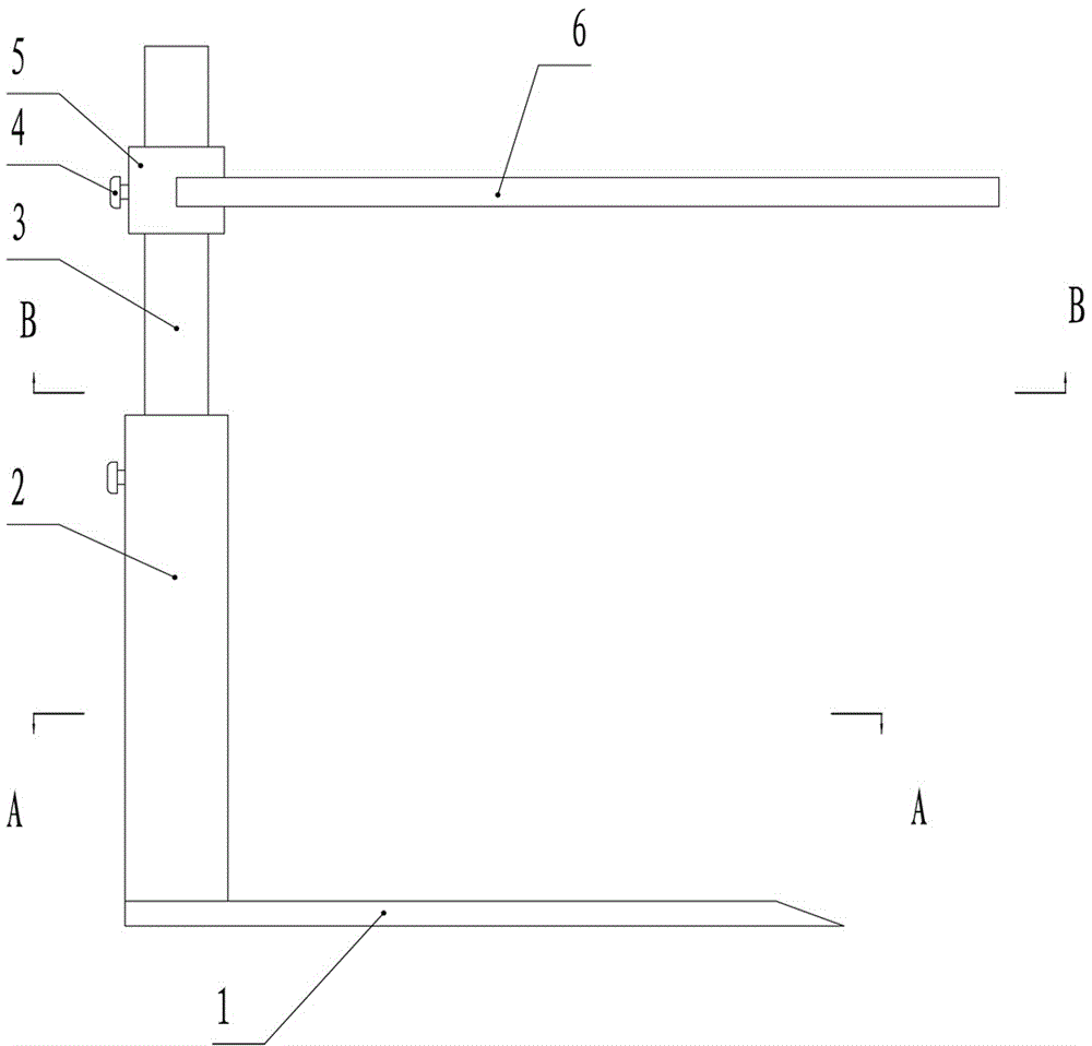
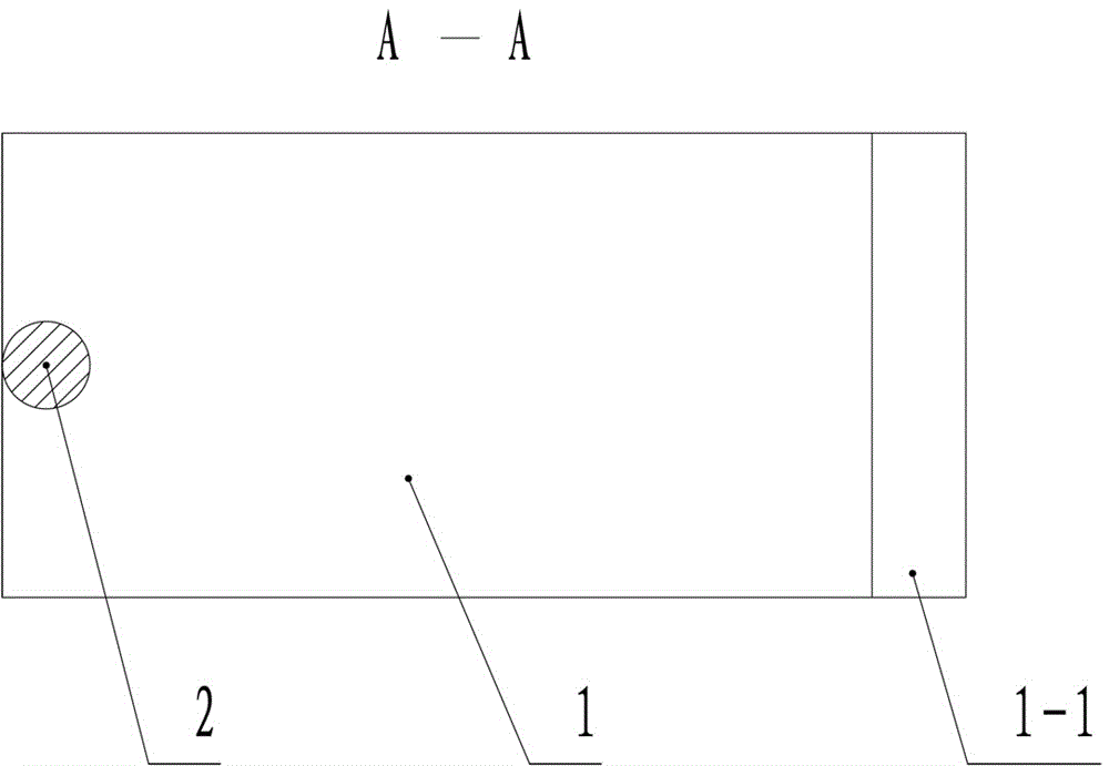
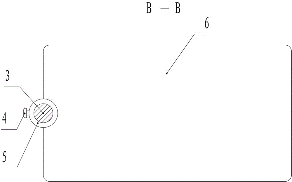
[0027] figure 1 , figure 2 and image 3 The wound decompression supporter comprises a base 1, a column 2 and a movable support rod 3 inserted into the column 2 at one end, the movable support rod 3 is covered with a rotary sleeve 5, and the rotary sleeve 5 is welded to the support member 6; the bottom end of the column 2 is connected to the The base 1 is threaded to facilitate the separation or connection of the column 2 and the base 1 during disassembly; the column 2 and the rotating sleeve 5 are all provided with locking parts; When raising or lowering the movable support rod 3, the movable support rod 3 is moved up and down along the column 2, and the locking piece used when moving to a suitable position is fixed and locked on the column 2, and the rotating sleeve 5 is also set to the suitable position. Fix and lock on the movable support bar 3 with the locking member 4 above it; the locking member of this embodiment is a bolt, and can be other forms of locking members i...

Embodiment 2

[0028] Example 2: Figure 4 , Figure 5 and Figure 6 The wound decompression supporter, the base 1 is a flat plate in the shape of "U", and the opening end of the flat plate in the shape of "U" is provided with a slope 1-1, such as Figure 5 As shown; the support member 6 is a rod member in the shape of a "U" that connects the swivel sleeve 5, such as Figure 6 As shown, the cover is covered on the rod during use; the rest of the structure and principle are the same as in Embodiment 1.

Embodiment 3

[0029] Example 3: Figure 7 and Figure 8 The wound decompression supporter, the support member 6 includes a longitudinal bar connected to both sides of the rotary sleeve 5 and a cross bar connected with the longitudinal bar, the cross bar is provided with a chute 6-1, and the two sides of the movable support plate 6-2 are inserted Be contained in the chute 6-1, when only cross bar support is required, the movable support plate 6-2 can be extracted. The base 1 can adopt the flat plate in the shape of "U" in the second embodiment, or the whole flat plate in the first embodiment; other structures and principles are the same as those in the first embodiment.


PUM


Abstract

The invention discloses a decompression support for wounds and relates to the field of auxiliary medical equipment for nursing patients. The decompression support comprises a base, an upright column and a movable support rod, wherein one end of the movable support rod is inserted into the upright column, and the movable support rod is sleeved with a rotary sleeve which is connected with a support piece; the bottom end of the upright column is connected with the base; locking pieces are arranged on the upright column and the rotary sleeve. The decompression support can solve the problem that rehabilitation of patients is affected due to the fact that wounds are easy to compress when patients staying in bed after surgery, particularly the patients subjected to penis surgery or major abdominal surgery are covered with quilts, and the problems about warm keeping, privacy protection and dignity guard during physiotherapy and acupuncture of the patients suffering from extensive burns or scalds and requiring exposure therapy can be solved.

Description

technical field [0001] The invention relates to the technical field of medical devices, in particular to a supporter used for preventing wound quilts from being touched when a patient is bedridden after surgery so as to achieve decompression of the wound. Background technique [0002] Patients need to rest in bed after operation, especially for patients with penile surgery, the wound site cannot touch clothing or bedding, but in order to keep warm and hide privacy, they have to cover the quilt to ensure the maintenance of body temperature and prevent wind and cold, but the perineal area It is a sensitive part of the human body. After penile surgery, any foreign objects will increase the pain and discomfort of the patient. When covering the quilt, the weight of the quilt itself will press on the patient's wound, causing wound pain and affecting the recovery of the patient's condition. The current solution is to put the edge of the whole quilt covered on the bed rails. In this...

Claims


Application Information

Patent Timeline
Patent Type & Authority Applications(China)
IPC IPC(8): A61G7/00A61G7/05
CPCA61G7/00A61G7/05A61G7/0501A61G2203/70
Inventor 陈桂红李文娟林柳晶韦英唐丽刘远金
Owner LIUZHOU PEOPLES HOSPITAL
Learn More