Fault information sampling device

A sampling system and fault information technology, which is applied in the direction of measuring devices, instruments, scientific instruments, etc., can solve the problems of low detection accuracy, affecting faults, and the detector cannot detect gas, so as to achieve accurate analysis and judgment of faults and improve accuracy Effect

Inactive Publication Date: 2016-10-05
HUNAN UNIV OF HUMANITIES SCI & TECH
View PDF0 Cites 0 Cited by
  • Summary
  • Abstract
  • Description
  • Claims
  • Application Information

AI Technical Summary

Problems solved by technology

When the existing detector detects gas, due to the fast gas flow rate, the detector cannot detect the gas very stably, resulting in low detection accuracy, which in turn affects the judgment of the fault problem

Method used


Image

  • Fault information sampling device
  • Fault information sampling device
  • Fault information sampling device

Examples


Embodiment Construction

[0014] The present invention will be further described below in conjunction with the accompanying drawings.

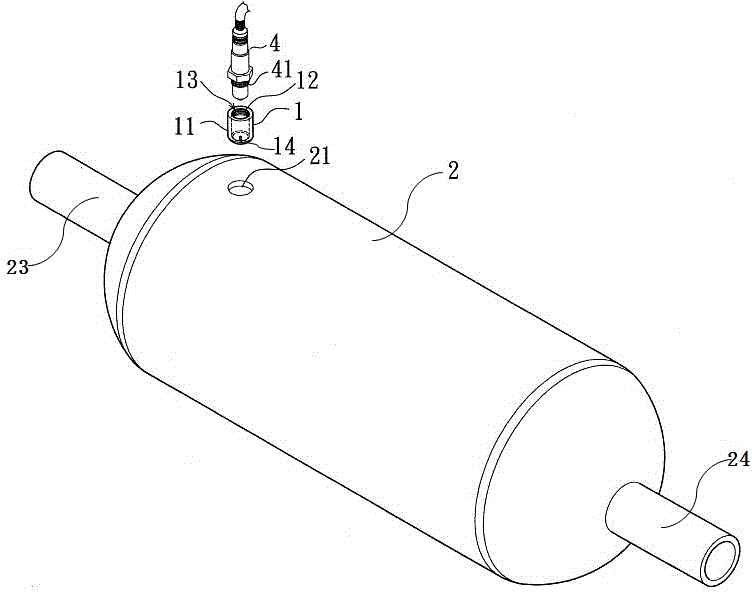
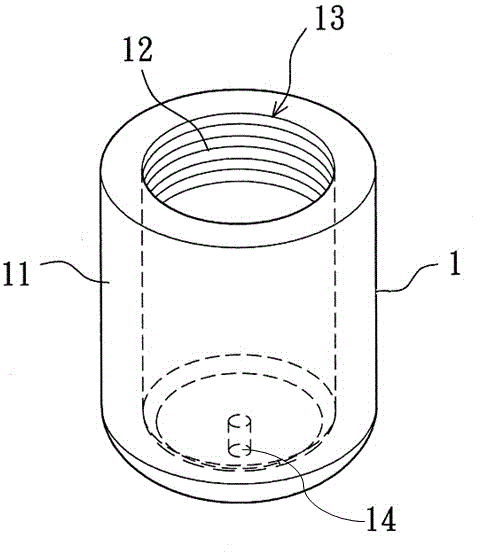
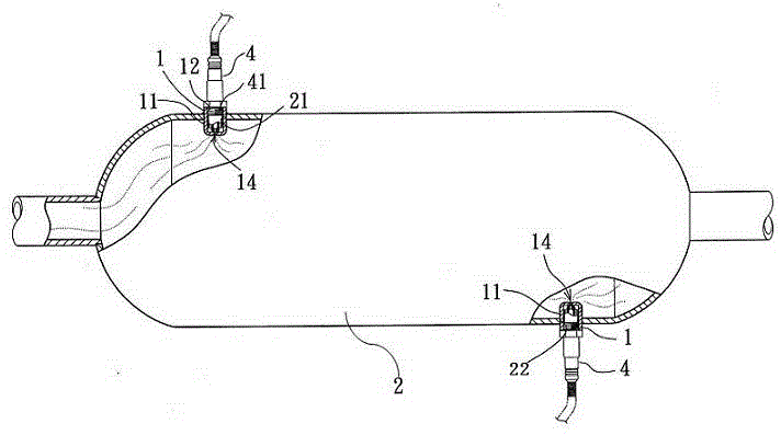
[0015] like figure 1 and image 3 As shown, the fault information sampling system of this embodiment includes a base 1, a converter 2 and a detector 4. The converter 2 is a cylinder, and a catalyst is provided inside the converter 2 for purifying the gas. The converter 2 includes a front-end pipe 23 and a rear-end pipe 24 at both ends, and the gas enters from the front-end pipe 23 and is discharged from the rear-end pipe 24 . The converter 2 is provided with a first hole 21 and a second hole 22 near the front and rear end pipes. In this embodiment, the first and second holes 21 and 22 are arranged on the surface of the cylinder of the converter 2 . The base 1 is respectively disposed in the first hole 21 and the second hole 22 , and the detector 4 is disposed in the base 1 . The base 1 includes a sleeve 11 with an internal thread 12 inside. The upper end of the slee...


PUM


Abstract

The invention relates to a fault information sampling device which comprises a converter and a detector, wherein the converter comprises a front-end pipe and a rear-end pipe; the detector is arranged on the converter; the fault information sampling device also comprises a base; a first hole and a second hole are formed in the converter and are respectively formed in two ends of the converter; the base is arranged in the first and second holes; the detector is arranged in the base; a through hole is formed in the bottom of the base; and a distance is formed between the through hole and the end of the detector. According to the fault information sampling device disclosed by the invention, gases in the converter enter the sleeve, so that the gases do not drift too fast, and the gases can be stably detected by the detector. Therefore, the detection accuracy is improved, and the failure can be accurately analyzed and judged.

Description

technical field [0001] The invention relates to a fault information sampling system. Background technique [0002] At present, the fault information sampling system of the engine usually uses sensors for detection, and determines whether there is a fault by analyzing and judging the detected data. For example, the treatment of the exhaust gas after the combustion of the engine usually needs to process the air through a catalytic converter, so as to reduce the pollution of the discharged gas to the air. By detecting the exhaust gas and the gas passing through the converter, the content of the exhaust gas and the content of pollutants in the purified gas can be judged, so as to determine whether the converter is working normally. When the existing detector detects gas, due to the fast gas flow rate, the detector cannot detect the gas very stably, resulting in low detection accuracy, which in turn affects the judgment of the fault problem. Contents of the invention [0003]...

Claims


Application Information

Patent Timeline
Patent Type & Authority Applications(China)
IPC IPC(8): G01N33/00G01M13/00
Inventor 江彤成运张丹华
Owner HUNAN UNIV OF HUMANITIES SCI & TECH
Why Eureka
Try Eureka