Automatic shaft feeding and rolling structure in continuous die

A reel and shaft feeding technology, which is applied in the field of mold manufacturing, can solve problems such as low efficiency, achieve convenient operation, improve work efficiency, and change the processing technology

Active Publication Date: 2016-10-05
XIANGYANG SUNRISE MACHINERY
View PDF5 Cites 2 Cited by
  • Summary
  • Abstract
  • Description
  • Claims
  • Application Information

AI Technical Summary

Problems solved by technology

Inefficiency, and there is a big security risk

Method used


Image

  • Automatic shaft feeding and rolling structure in continuous die
  • Automatic shaft feeding and rolling structure in continuous die
  • Automatic shaft feeding and rolling structure in continuous die

Examples


Embodiment Construction

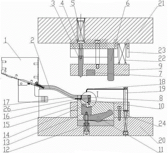
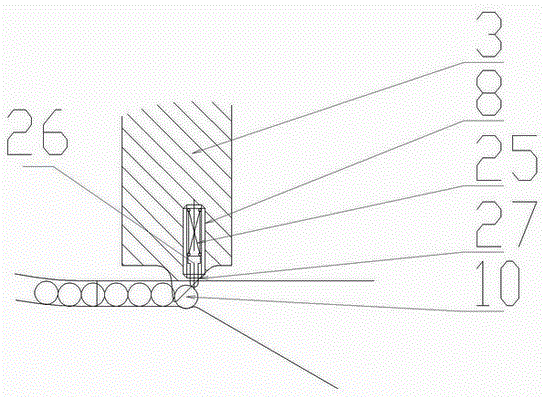
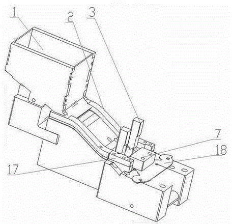
[0013] Such as figure 1 , figure 2 , image 3 As shown, the upper mold stripping plate 9 of the present invention is connected with the upper mold 21 through the spring two 22, and the upper mold stripping plate 9 is inlaid with a stripping plate insert 7; On the die 21; the push rod 3 is connected with the upper die 21 by a contour screw-4, a spring-5, and the bottom of the push rod 3 has a slope 27 for promoting the shaft 10.

[0014] The sheet metal part 18 is connected to the lower mold 20 through the spring three 24 through the floating material pin 19; the ejector pin installation block 17 is connected to the shaft placement groove 15 through the shaft stopper 16, and the ejector pin installation block 17 and the shaft stopper 16 are respectively two , symmetrically fixed on both sides of the shaft 10; the ejector pin 8 is fixed by threads in the ejector pin mounting block 17, the ejector pin 26 in the inner hole of the ejector pin 8 is connected with the ejector pin ...


PUM


Abstract

The invention discloses an automatic shaft feeding and rolling structure in a continuous die and relates to the technical field of machining. A storage box provided with a shaft is put on a worktable, the storage box is connected with a sliding rail, and the shaft is pushed into a shaft containing groove in a lower die through a push rod on an upper die via the sliding rail. A shaft rolling insert is connected to the lower die through a fourth spring and a second equal-height screw. A swing block is hinged to the shaft containing groove. The upper die descends, an upper die stripper plate is used for pressing a floating material pin to descend so as to drive a sheet metal part to descend. The swing block push rod on the upper die is pressed on the swing block, the swing block drives the shaft rolling insert to upwards move, and the sheet metal part and the shaft are rolled and pressed to be formed in the shaft rolling insert. By means of the automatic shaft feeding and rolling structure in the continuous die, traditional single-time punching and automatic shaft feeding and rolling are integrated, the shaft can be automatically conveyed and rolled and pressed in the continuous die, manual shaft putting is effectively avoided, the working efficiency is improved, the machining technology of a hardware punched part is changed, the structure is simple, operation is convenient, the production cost is low, and the automatic shaft feeding and rolling structure can be applied to various sheet metal shaft rolling parts.

Description

technical field [0001] The invention relates to the technical field of mold manufacturing, in particular to a structure for sheet metal parts such as automobiles, hardware and electronic products, which automatically feeds a shaft and a reel while stamping the parts. Background technique [0002] At present, my country's mold industry is in a stage of rapid development. As many as 60%-90% of modern industrial products are molded using molds, especially in the fields of automobiles, electronics, and electrical appliances. Due to the incomparable advantages of other processing methods such as high precision, high complexity, high uniformity and high efficiency in mold forming, the development level of the mold industry has gradually become an important symbol to measure the manufacturing level. However, for parts with a reel on the part, the original process is a separate reel, and the operator places a part and a shaft one after another before stamping. The efficiency is low...

Claims


Application Information

Patent Timeline
Patent Type & Authority Applications(China)
IPC IPC(8): B21D37/10B21D43/05B21D35/00
Inventor 宋吉海喻伟
Owner XIANGYANG SUNRISE MACHINERY
Why Eureka
Try Eureka