DC power supply units, motor drives and refrigeration cycle applications
A DC power supply and motor technology, which is applied in AC motor control, motor generator control, lighting and heating equipment, etc., can solve the problem of increasing switching loss, and achieve the effects of simple control, high boost ratio, and high efficiency.
- Summary
- Abstract
- Description
- Claims
- Application Information
AI Technical Summary
Problems solved by technology
Method used
Image

Examples
Embodiment approach 1
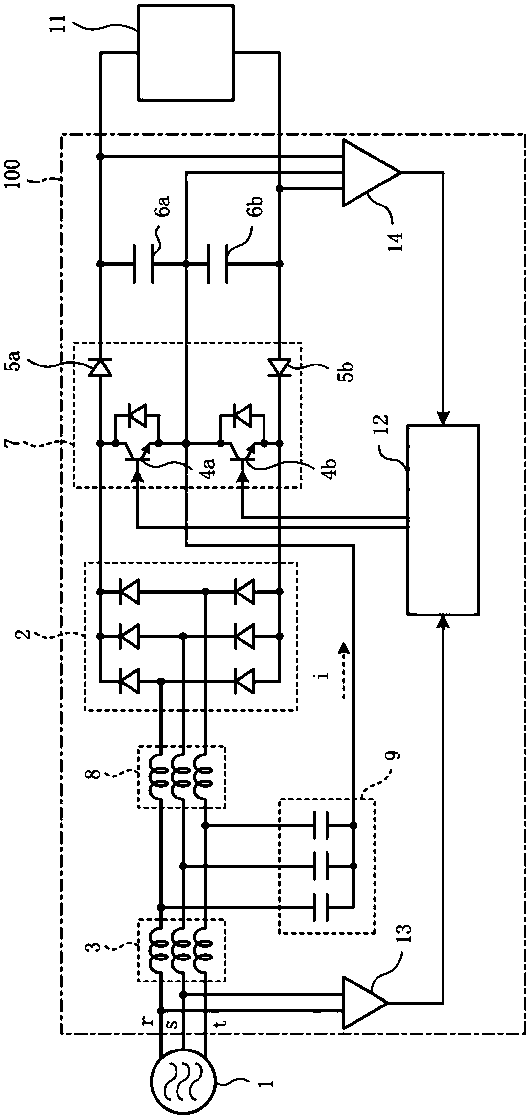
[0057] figure 1 is a diagram showing an example of the configuration of the DC power supply device according to the first embodiment. like figure 1 As shown, the DC power supply device 100 according to Embodiment 1 is configured to convert the three-phase AC supplied from the AC power supply 1 into DC and supply it to the load 11 according to the operating state of the load 11 . In addition, in this embodiment, although the inverter load etc. which drive the motor of the compressor used for a refrigeration cycle apparatus were assumed as load 11, it is obvious that it is not limited to this.
[0058] The DC power supply device 100 is provided with: a rectifier circuit 2 which rectifies the three-phase AC; stage, and each phase of the three-phase AC is respectively inserted between the AC power source 1 and the rectifier circuit 2; the first capacitor 6a and the second capacitor 6b, which are connected in series between the output terminals to the load 11; as the first switch...
Embodiment approach 2
[0105] Figure 5 It is a figure which shows an example of a structure of the DC power supply apparatus concerning Embodiment 2. In addition, the same code|symbol is attached|subjected to the same or equivalent structural part as Embodiment 1, and the detailed description is abbreviate|omitted.
[0106] Figure 5 The shown DC power supply device 100a according to the present embodiment is constituted by reactors 50, 51, 52 provided in respective phases, wherein the reactors 50, 51, 52 are the ones described in the first embodiment. figure 1 In the shown structure, the first reactor 3 and the second reactor 8 are magnetically coupled to each other and are magnetically coupled reactors.
[0107] By employing such a configuration, it is possible to reduce the volume of space occupied by the reactor when configuring the DC power supply device 100a. In particular, if the reactor 50 , 51 , 52 is provided with an intermediate tap connected to the capacitor bank 9 , it can be config...
Embodiment approach 3
[0113] Image 6 is a diagram showing an example of the configuration of a DC power supply device according to Embodiment 3. In addition, the same code|symbol is attached|subjected to the same or equivalent structural part as Embodiment 1, and the detailed description is abbreviate|omitted.
[0114] like Image 6 As shown, in the DC power supply device 100b according to the third embodiment, in addition to the figure 1 In addition to the structure shown, the midpoint of the series circuit formed by the first switching element 4a and the second switching element 4b and the midpoint of the series circuit formed by the first capacitor 6a and the second capacitor 6b pass through as a neutral line. The on-off unit 20 of the open unit is connected.
[0115] In the structures of Embodiments 1 and 2 without the on-off unit 20, if any one of the first anti-backflow element 5a, the second anti-backflow element 5b, the first switching element 4a and the second switching element 4b fail...
PUM
 Abstract
Description
Claims
Application Information
 - R&D
- Intellectual Property
- Life Sciences
- Materials
- Tech Scout
- Unparalleled Data Quality
- Higher Quality Content
- 60% Fewer Hallucinations
Browse by: Latest US Patents, China's latest patents, Technical Efficacy Thesaurus, Application Domain, Technology Topic, Popular Technical Reports.
© 2025 PatSnap. All rights reserved.Legal|Privacy policy|Modern Slavery Act Transparency Statement|Sitemap|About US| Contact US: help@patsnap.com