
Nano indentation testing device under stretch-four-point bending preload

A four-point bending and nano-indentation technology, which is applied in the direction of measuring devices, instruments, scientific instruments, etc., can solve the problems of large dispersion, unfavorable function expansion, and lack of methods for evaluating the accuracy of mechanical parameter testing, and achieves compact structure, volume small effect

Inactive Publication Date: 2016-09-28
CHANGCHUN UNIV OF TECH
View PDF8 Cites 22 Cited by
  • Summary
  • Abstract
  • Description
  • Claims
  • Application Information

AI Technical Summary

Problems solved by technology

At present, most of the mechanical testing machines on the market are non-situ universal testing machines for structural materials. One test can only realize the loading of one kind of load. During the test, only the load and displacement values ​​of the specimen can be recorded. Changes in microscopic morphology are lacking in records
Most of the existing in-situ testing instruments only have the test function of a single load, such as in-situ tensile testers, in-situ nano-indentation testers and in-situ bending testers, etc., and nano-indentation testers under composite loads There are few reports, and at the same time, there is a lack of effective evaluation methods for the accuracy of mechanical parameter testing
On the whole, the main problems exposed during the use of existing testing instruments are: firstly, the repeatability of the test results is not good, and the dispersion is large; The requirement of multi-physics is not conducive to the expansion of functions; finally, the test instruments are not capable of testing new structural materials and advanced functional materials.
[0003] Due to the lack of indentation test instruments under compound loads, there are relatively few indentation tests for materials under preload at home and abroad. mark testing equipment

Method used


Image

  • Nano indentation testing device under stretch-four-point bending preload
  • Nano indentation testing device under stretch-four-point bending preload
  • Nano indentation testing device under stretch-four-point bending preload

Examples


Embodiment Construction

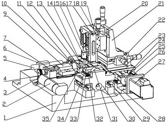
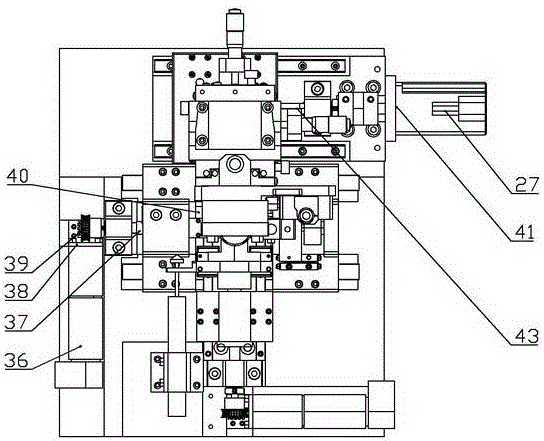
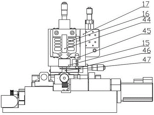
[0022] see Figure 1 to Figure 4 As shown, the present invention includes a tensile preload loading mechanism, a four-point bending preload loading mechanism and an in-situ nano-indentation testing mechanism.

[0023] The precision DC servo motor 36 in the tensile preload loading mechanism is fixedly installed on the test platform base 1 through the motor flange 38, and forms a first-stage deceleration and commutation with the worm gear II 39. The bi-directional ball screw nut pair 37 converts the rotary motion of the worm gear worm pair II 39 into a synchronous two-way linear motion, and then drives the specimen fixture support seat Ⅰ14 and fixture support seat Ⅱ30 installed on the nut pair to realize synchronous two-way linear motion, and the specimen fixture The support base I14 and the clamp support base II30 are installed on the linear guide rail 29 of the stretching mechanism below, wherein the clamp II34 is connected with the force sensor 31 of the stretching mechanism ...


PUM


Abstract

The invention discloses a nano indentation testing device under a stretch-four-point bending preload. The nano indentation testing device integrates a pure-stretch test, a pure four-point bending test and a composite load test based on the two single load forms, and meanwhile a nano indentation testing mechanism is integrated on the basis of stretch-four-point bending. A testing platform is composed of a precise stretch preload drive transmission unit and detection and clamping unit, a precise four-point bending preload drive transmission unit and clamping and detection unit and the like. The in-situ nano indentation testing mechanism comprises an X-direction displacement platform, a Y-direction displacement platform, a Z-direction displacement platform, a piezoelectric stack, a flexible hinge, a pressure sensor, a displacement sensor, a diamond indenter clamping bar and the like. The nano indentation testing device is small in size, compact in structure and capable of conducting an experimental test under an optical microscope through real-time microscopic observation, an in-situ bending composite test can be utilized to obtain mechanical property parameters of a material, and in-situ monitoring is conducted on microscopic deformation, damage and the fracture process of the material.

Description

technical field [0001] The invention relates to the field of in-situ mechanical performance testing, in particular to a nano-indentation testing device under tensile-four-point bending preload. It can be used independently as a cross-scale in-situ material performance testing platform for pure tensile loading mechanism, pure four-point bending loading mechanism, and in-situ nano-indentation testing mechanism. It can also be used for simultaneous composite loading of multiple loads. Background technique [0002] The working environment of various materials and their products during service is relatively complex, and it is rare that they are subjected to a single load, and more often they are subjected to the joint action of multiple physical fields and multiple loads. Due to the effect of composite load, the material often fails to reach the service limit, and failure will occur. Therefore, it is very important to develop an instrument that can test the micromechanical prope...

Claims


Application Information

Patent Timeline
Patent Type & Authority Applications(China)
IPC IPC(8): G01N3/02
CPCG01N3/02
Inventor 崔利娜尤元关常君邵珠超李瑞
Owner CHANGCHUN UNIV OF TECH
Learn More