
Circulating pump pipeline

A circulating pump and pipeline technology, applied in the field of heating unit equipment, can solve the problems of damaged circulating pump, large impact force of circulating pump, water hammer, water hammer, etc., and achieve impact mitigation, high reliability, and extended service life Effect

Inactive Publication Date: 2016-09-28
天津地热开发有限公司
View PDF6 Cites 1 Cited by
  • Summary
  • Abstract
  • Description
  • Claims
  • Application Information

AI Technical Summary

Problems solved by technology

In this way, when the system suddenly stops working due to power failure or other external factors, the water in the system will continue to move forward due to inertia, and the impact force of the water flow on the circulating pump is very large. Water hammer phenomenon, damage the circulation pump

Method used


Image

  • Circulating pump pipeline

Examples


Embodiment Construction

[0008] Below in conjunction with accompanying drawing and specific embodiment the present invention will be described in further detail:

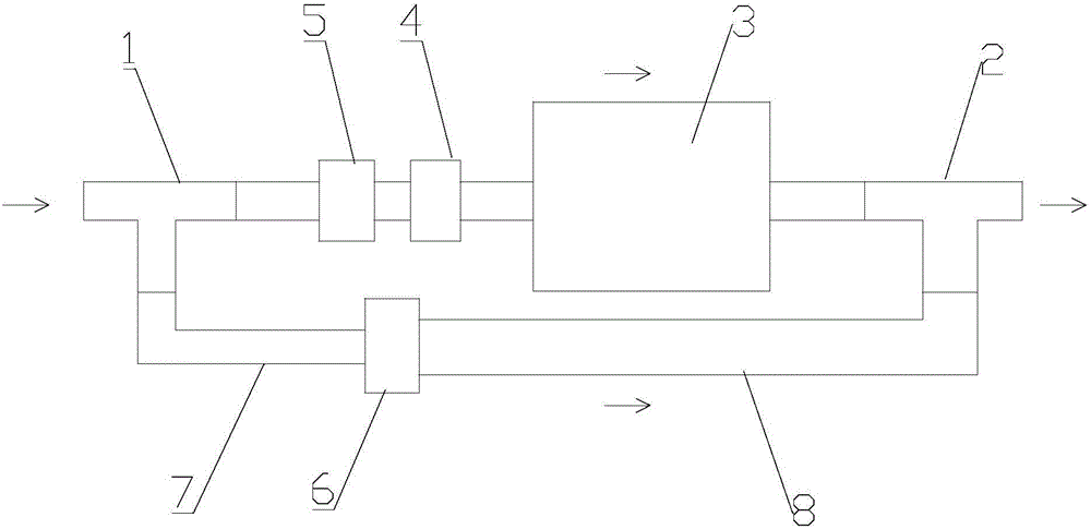
[0009] see figure 1 , the circulating pump pipeline of the present invention includes a water inlet tee 1 and a water outlet tee 2 installed on the circulation pipeline, and a circulation pump 3 and a bypass pipe are respectively connected between the water inlet tee 1 and the water outlet tee 2 , the connecting pipe between the circulation pump 3 and the water inlet tee 1 is provided with a direct-acting solenoid valve 4, and the connecting pipe between the direct-acting solenoid valve 4 and the water inlet tee 1 is provided with a drain pressure valve 5, and a one-way valve 6 is provided on the bypass pipe. After the system is powered off, the circulation pump 3 suddenly stops working. At this time, the direct-acting solenoid valve 4 closes the pipeline between the circulation pump 3 and the water inlet tee 1 due to power failure, and th...


PUM


Abstract

The invention discloses a circulation pump pipeline, which includes a water inlet tee and a water outlet tee installed on the circulation pipeline, and a circulation pump and a bypass pipe are respectively connected between the water inlet tee and the water outlet tee. The connecting pipe between the circulation pump and the water inlet tee is provided with a direct-acting solenoid valve, and the connecting pipe between the direct-acting solenoid valve and the water inlet tee is provided with a pressure relief valve. A one-way valve is arranged on the through pipe. When the circulation pump stops working suddenly, part of the water flows out from the bypass pipe, which alleviates the impact of the water flow on the circulation pump, thereby avoiding the occurrence of water hammer and water hammer, and prolonging the service life of the circulation pump. The invention has a simple structure and Strong reliability.

Description

technical field [0001] The invention relates to a heating unit equipment, in particular to a circulation pump pipeline. Background technique [0002] The function of the circulating pump in the heating unit is to provide the power of the secondary circulating water to make the water in the secondary side of the unit flow, so as to exchange heat with the water in the primary side in the heat exchanger. The water flow on the secondary side of the existing unit all flows into the circulation pump, and no bypass circuit is installed. In this way, when the system suddenly stops working due to power failure or other external factors, the water in the system will continue to move forward due to inertia, and the impact force of the water flow on the circulating pump is very large. Water hammer phenomenon, damage the circulation pump. Contents of the invention [0003] The technical problem to be solved by the present invention is to provide a circulation pump pipeline with simpl...

Claims


Application Information

Patent Timeline
Patent Type & Authority Applications(China)
IPC IPC(8): F24D3/02
CPCF24D3/02
Inventor 李力刘艳韩胜
Owner 天津地热开发有限公司
Learn More