Integrated spraying maintenance system and method for U-beam body
A maintenance system and an integrated technology, which is applied in the field of U-shaped beam integrated spray maintenance system, can solve the problems of untimely maintenance, uneven spraying, and high labor intensity, so as to reduce repeated spraying and improve spraying. The effect of spraying quality and high maintenance precision
- Summary
- Abstract
- Description
- Claims
- Application Information
AI Technical Summary
Problems solved by technology
Method used
Image
Examples
Embodiment 1
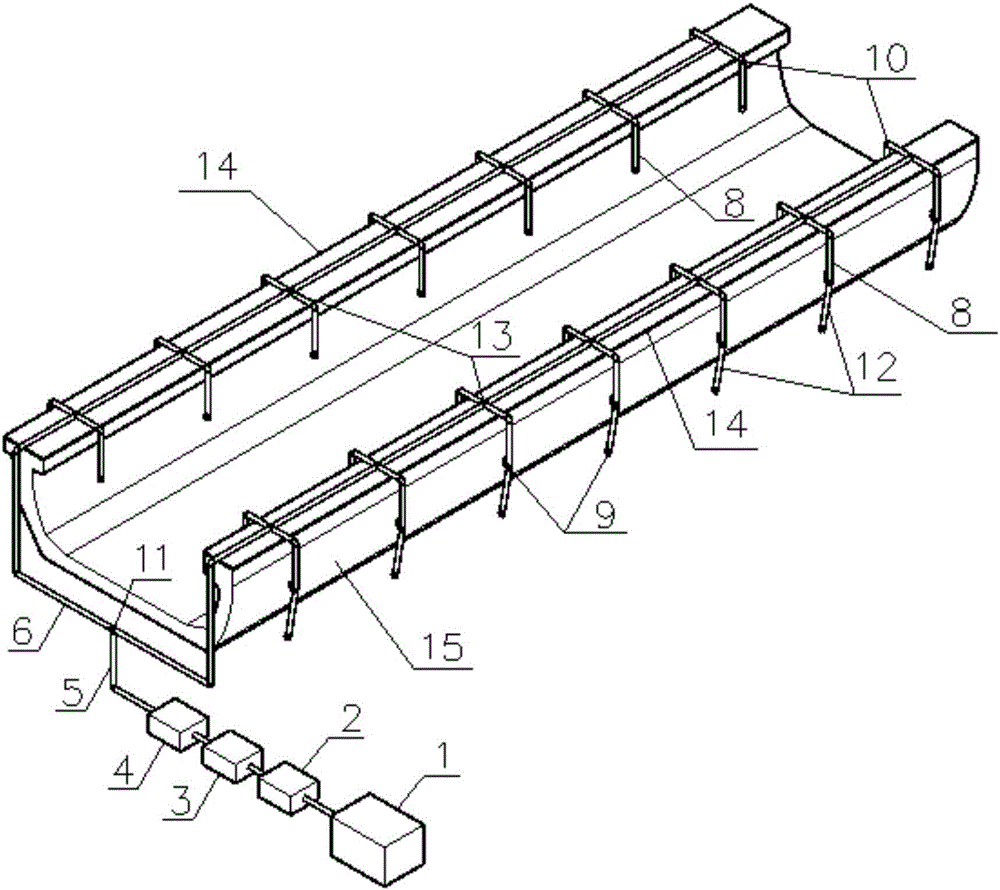
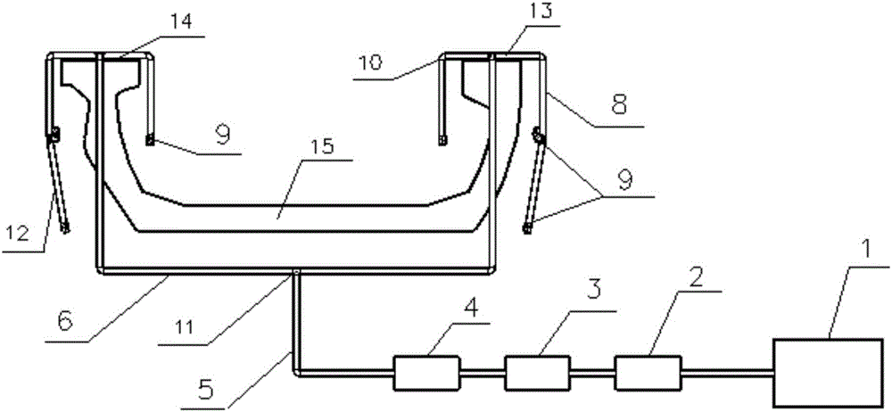
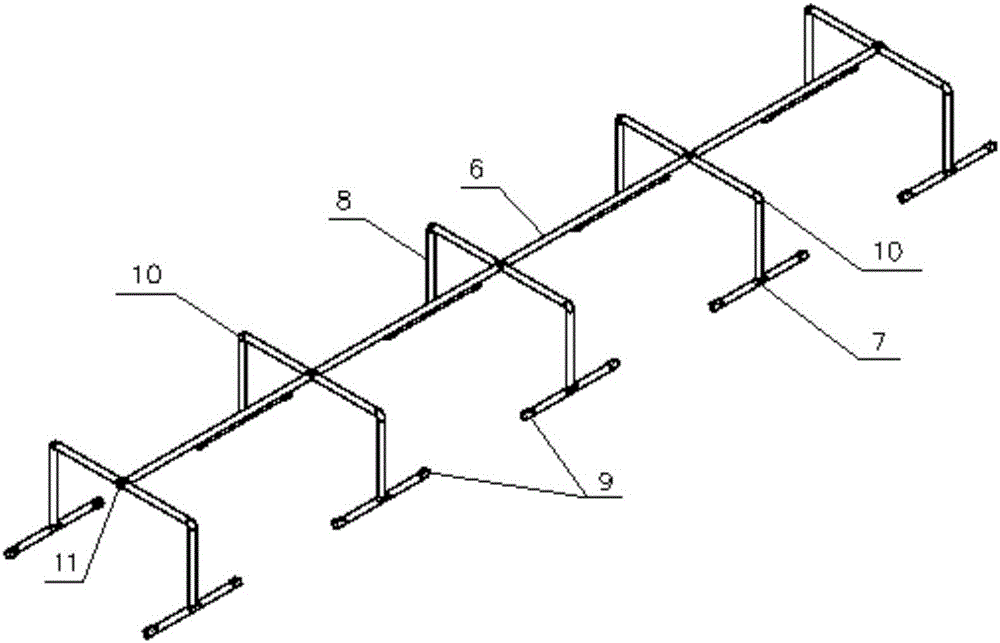
[0028] The prefabricated U-shaped beam 15 has been set on the special prefabricated U-shaped beam pedestal, and the spray maintenance system is connected in turn, including the reservoir 1 with a specific water source inside, the frequency conversion booster pump 2, the water supply control system, and the special PPR maintenance water supply pipeline network. Such as figure 1 As shown, the water supply pipeline includes a first pipeline 5 as a water supply skeleton pipeline, the first pipeline 5 is provided with two symmetrically arranged second pipelines, and the direction adjustment joint 10 in the middle of the second pipeline is L-shaped. The top of the second pipeline 6 is provided with a third pipeline through the branch joint 7, and the third pipeline is arranged along the upper end surfaces on both sides of the long axis of the U-shaped beam 15 and is effectively bonded, and the third pipeline includes a plurality of The branched fourth pipeline 13, the nozzle 9 is a...
Embodiment 2
[0034]The U-shaped beam body integrated spray maintenance system includes a water supply pipeline arranged in the U-shaped beam. The water supply pipeline includes a first pipeline arranged roughly along the center of the inner bottom plate of the U-shaped beam. The branched second pipeline is provided with multiple nozzles for spraying the inner and outer surfaces of the U-shaped beam; the water source flows in from the first pipeline and flows out through the multiple nozzles of the branched second pipeline, Realize the spraying on the U-shaped beam body and avoid the traditional artificial spraying, which not only saves time, but also sprays more evenly.
[0035] For spray uniformity, such as image 3 and Figure 4 As shown, the second pipeline is L-shaped, the second pipeline is arranged along the end surface of the U-shaped beam, and the top of the second pipeline is provided with a third pipeline, so that each of the end surfaces on both sides of the U-shaped beam is se...
Embodiment 3
[0037] The difference between this embodiment and embodiment 2 is:
[0038] The second pipeline is L-shaped, the top of the second pipeline is provided with a third pipeline, and a plurality of nozzles are arranged on the third pipeline to spray the U-shaped beam, and the spray nozzles on the third pipeline realize the spraying of the U-shaped beam. The profile beam is sprayed from high to low.
[0039] Since the outer side of the web of the U-shaped beam body is relatively high, considering that the overweight of the maintenance branch pipeline unit will affect the overall safety of the structure, which may endanger the maintenance quality of the U-shaped beam body, a third pipeline is specially set up, using direct connectors. Realize the connection of the second pipeline and the third pipeline, thereby adjusting the two-way spraying in Embodiment 1 to one-way lengthening spraying.
PUM
 Abstract
Description
Claims
Application Information
 - R&D
- Intellectual Property
- Life Sciences
- Materials
- Tech Scout
- Unparalleled Data Quality
- Higher Quality Content
- 60% Fewer Hallucinations
Browse by: Latest US Patents, China's latest patents, Technical Efficacy Thesaurus, Application Domain, Technology Topic, Popular Technical Reports.
© 2025 PatSnap. All rights reserved.Legal|Privacy policy|Modern Slavery Act Transparency Statement|Sitemap|About US| Contact US: help@patsnap.com


