
Efficient sludge incinerator

A sludge incineration and high-efficiency technology, applied in incinerators, combustion methods, combustion types, etc., can solve the problems of incineration, insufficient combustion air, and inability to obtain sludge particles, and achieve the effect of improving efficiency.

Inactive Publication Date: 2016-09-21
江苏全能环保设备有限公司
View PDF6 Cites 8 Cited by
  • Summary
  • Abstract
  • Description
  • Claims
  • Application Information

AI Technical Summary

Problems solved by technology

Although the combustion-supporting air can be mixed with the sludge particles to be incinerated under the agitation of the stirring device, the combustion-supporting air entering the furnace body is often not sufficient due to the limitation of the inlet position of the combustion-supporting air, and it is impossible to realize the mixing with the sludge particles to be incinerated. Uniform mixing, so that the sludge particles in the furnace cannot be completely incinerated, so that the efficiency of sludge incineration is greatly limited

Method used


Image

  • Efficient sludge incinerator

Examples


Embodiment Construction

[0014] The present invention will be described in further detail below in conjunction with the accompanying drawings.

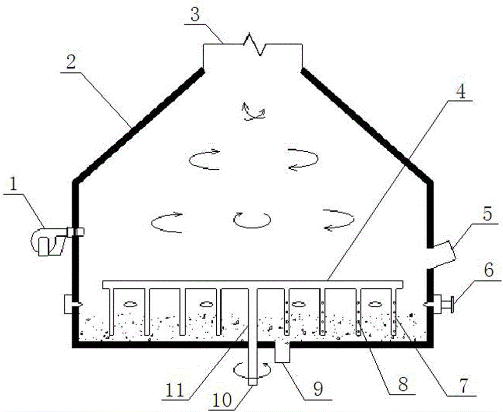
[0015] Such as figure 1 As shown, the high-efficiency sludge incinerator of the present invention includes a furnace body 2, which is cylindrical and vertically arranged. The bottom of the furnace body 2 is closed and the top has a waste gas outlet 3. In this embodiment, the upper part of the furnace body 2 is conical, and its top opening forms the exhaust gas outlet 3 . There is a stirring device at the bottom of the inner cavity of the body of furnace 2 , a feed port 5 and a burner 1 are arranged on the side wall of the body of furnace 2 above the stirring device, and an ash outlet 9 is arranged at the bottom of the body of furnace 2 . The stirring device is a hollow steel pipe structure, and there is an air inlet 10 at one end protruding from the bottom of the furnace body 2 , and an air outlet 8 is arranged on the stirring device inside the furnace body ...


PUM


Abstract

The invention relates to incineration equipment, in particular to an efficient sludge incinerator capable of allowing sludge to be incinerated fully. The efficient sludge incinerator comprises an incinerator body which is cylindrical and is arranged vertically, wherein the bottom of the incinerator body is sealed; an exhaust gas outlet is formed in the top of the incinerator body; a mixing device is arranged at the bottom of an inner cavity of the incinerator body; a feed port and a burner are formed and arranged in the side wall of the incinerator body above the mixing device; and an ash outlet is formed in the bottom of the incinerator body. The efficient sludge incinerator is characterized in that the mixing device is in a hollow steel pipe structure; an air inlet is formed in one end, stretching out of the bottom of the incinerator body, of the efficient sludge incinerator; and an air outlet is formed in the mixing device positioned in the incinerator body. According to the efficient sludge incinerator, combustion-supporting air entering the incinerator body can be sufficient, and can be uniformly mixed with to-be-incinerated sludge particles, so that the sludge particles in the incinerator body can be incinerated completely, and the sludge incineration efficiency can be improved greatly.

Description

technical field [0001] The invention relates to an incineration equipment, in particular to a high-efficiency sludge incinerator capable of fully incinerating sludge. Background technique [0002] It is known in the incineration industry that the sludge incinerator is a device that can heat and dry the dewatered sludge, and oxidize the organic matter in the sludge with high temperature, so that the sludge becomes a small amount of ash. [0003] A traditional sludge incinerator includes a furnace body, which is cylindrical and vertically arranged, with a closed bottom and a waste gas outlet at the top; a stirring device is provided at the bottom of the inner cavity of the furnace body, and one side of the stirring device There is a combustion-supporting air inlet on the side wall of the furnace body, a feed inlet and a burner on the side wall of the furnace body above the stirring device, and an ash outlet at the bottom of the furnace body. When this sludge incinerator is in...

Claims


Application Information

Patent Timeline
IPC IPC(8): F23G7/00B01F7/18B01F15/02
CPCF23G7/00F23G2209/12B01F27/074B01F27/191B01F27/90B01F35/712
Inventor 张建平杭兵
Owner 江苏全能环保设备有限公司
Learn More