Threaded pump

A threaded pump and thread technology, applied in the field of hydraulic pumps, can solve the problems of large installation size, complex structure, high manufacturing accuracy and high cost, and achieve the effects of stable pressure, continuous and uniform liquid output, and convenient use and maintenance.

Inactive Publication Date: 2016-09-21
SHAANXI FAST GEAR CO
View PDF7 Cites 2 Cited by
  • Summary
  • Abstract
  • Description
  • Claims
  • Application Information

AI Technical Summary

Problems solved by technology

Although the lubricating effect is better, the traditional hydraulic pump has complex structure, large installation size, high manufacturing precision and cost

Method used


Image

  • Threaded pump
  • Threaded pump
  • Threaded pump

Examples


Embodiment Construction

[0019] The present invention will be further described in detail below in conjunction with specific embodiments, which are explanations of the present invention rather than limitations.

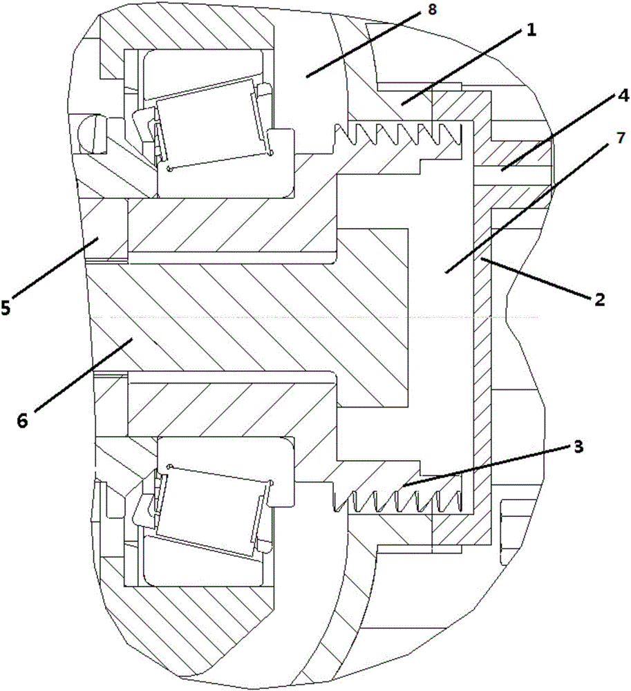
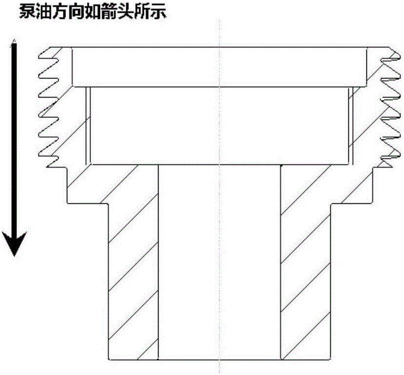
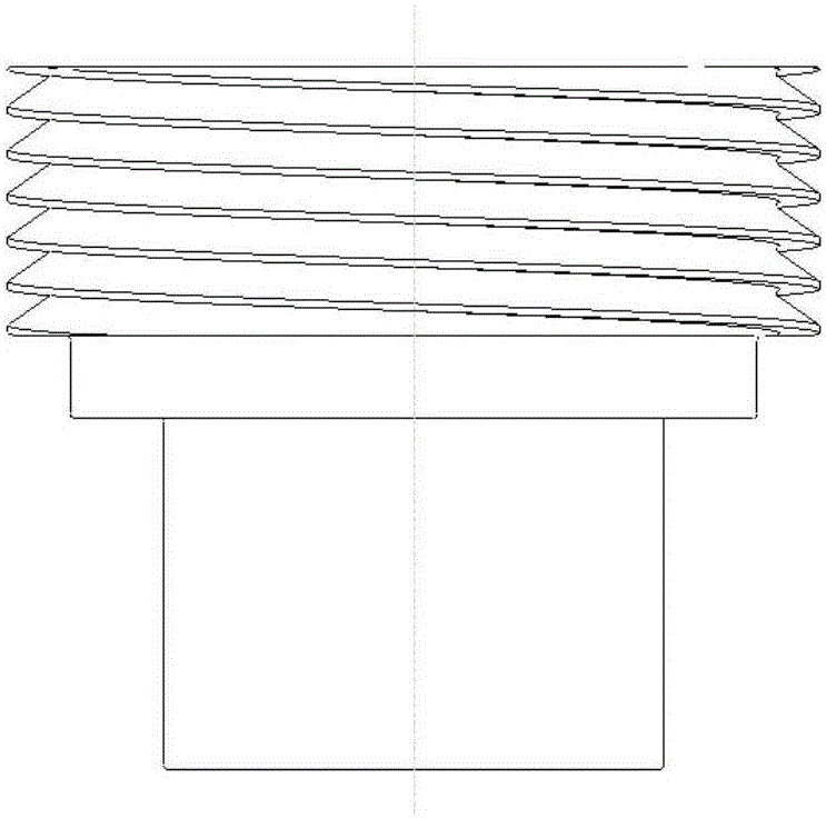
[0020] The invention relates to a threaded pump, which is a threaded hydraulic pump and plays the role of pumping oil. Such as figure 1 As shown, the threaded pump consists of a threaded pump housing 1, a threaded pump cover 2 and a threaded pump body 3. The threaded pump body 3 is connected with the rotating shaft 5 through a tension bolt 6 . The left end of the threaded pump body 3 is in the first cavity 7 , and the right end is in the second cavity 8 . The structure of threaded pump body 3 is as figure 2 and image 3 As shown, the outer circle of the threaded pump body 3 is threaded. If the pump body rotates clockwise from the oil pump direction, the thread should be left-handed, otherwise it should be right-handed. The thread profile should be a right triangle shape, such as figur...


PUM


Abstract

The invention discloses a threaded pump. The threaded pump is simple in structure, safe in work, high in reliability, convenient to use and maintain, continuous and uniform in liquid outlet and stable in pressure. The threaded pump comprises a threaded pump shell, a threaded pump cover and a threaded pump body, wherein the threaded pump shell is provided with an installation opening; the threaded pump cover is fixed to the installation opening in a matched manner; and the threaded pump body is matched with the threaded pump shell and the threaded pump cover in inner diameter. A thread is machined on the outer circle of the threaded pump body. The inner circle of the threaded pump shell and the inner circle of the threaded pump cover are unthreaded holes and cooperate with the outer circle face of the threaded pump body to form a spiral groove. One end face of the threaded pump body is connected with a rotating shaft, and the other end of the threaded pump body is provided with a groove. The exterior of the threaded pump body and the threaded pump shell form a second cavity. The threaded pump cover is provided with an oil inlet matched with a one-way valve; and the inner side of the threaded pump cover and the groove of the threaded pump body form a first cavity. The first cavity communicates with the second cavity through the spiral groove. When the threaded pump works, the threaded pump body rotates in the threaded pump shell and the threaded pump cover, and oil liquid is pumped into the second cavity from the first cavity.

Description

technical field [0001] The invention relates to a hydraulic pump, in particular to a threaded pump. Background technique [0002] Since the retarder is equipped with a heat exchanger for cooling the oil, the oil resistance is large, and the oil circulation is not smooth when the retarder is idling, which may easily cause poor lubrication of the internal components of the retarder. At present, in the field of hydraulic retarder, the following solutions are mainly adopted to solve the lubrication problem of internal components when the retarder is idling: 1. Set up a special idling lubricating oil channel to reduce oil resistance. 2. Add a hydraulic control valve to control the oil flow direction when the retarder is idling, so that the oil does not pass through the heat exchanger, but flows to the parts that need to be lubricated. 3. Add a forced lubricating oil pump. When the retarder is idling, the oil pump sucks a small amount of oil to lubricate the internal components. ...

Claims


Application Information

Patent Timeline
Patent Type & Authority Applications(China)
IPC IPC(8): F16N13/20
CPCF16N13/20F16N2013/205F16N2210/14
Inventor 孙博王伟健
Owner SHAANXI FAST GEAR CO
Why Eureka
Try Eureka