Unidirectional conversion device and power system comprising same

A technology of conversion device and power system, which is applied in the direction of generating mechanical power, engine components, machines/engines, etc., can solve the problem of low energy absorption and conversion efficiency, low cost input and output benefit, and insufficient ability to resist natural disasters, etc. problems, to achieve the effects of low construction and maintenance costs, strong resistance to natural disasters, and high mechanical conversion efficiency

Inactive Publication Date: 2016-09-21
吴钦发
View PDF7 Cites 1 Cited by
  • Summary
  • Abstract
  • Description
  • Claims
  • Application Information

AI Technical Summary

Problems solved by technology

The sea has inexhaustible green renewable energy. In the past century, many countries have invested a lot of money and talents in the research and development of ocean power generation. Most of the marine power generation equipment has low energy absorption and conversion efficiency, high manufacturing cost, and insufficient ability to resist natural disasters, which has caused the marine power generation industry to fail to enter industrial development for a long time
[0003] The Chinese invention patent number is 201010561662.8. The patent name is a wave power generation method and a system for implementing this method. This invention uses the float to swing and float under the action of waves to drive the one-way conversion device to do one-way rotation power generation. Although the invention has better performance The wave energy is directly driven by the generator components in the form of mechanical energy to generate electricity. However, due to the instability of the wave energy direction in the ocean, it can only absorb the back and forth kinetic energy of the wave in one direction. If it is necessary to absorb the side kinetic energy of the wave and multi-angle Wave energy needs to install more power generation devices at different angles and directions at the same time, resulting in low wave absorption efficiency of the invention, low cost input and output benefits, etc.

Method used


Image

  • Unidirectional conversion device and power system comprising same
  • Unidirectional conversion device and power system comprising same
  • Unidirectional conversion device and power system comprising same

Examples


Embodiment Construction

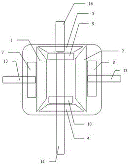
[0054] The present invention will be further described below in conjunction with accompanying drawing:

[0055] The one-way conversion device of the present invention is as attached Figure 1-4 And attached Figure 14As shown; the one-way conversion device 22 includes: a first swing input shaft 13 that can be connected to a front and rear swing power source; a second swing input shaft 14 that can be connected to a left and right swing power source; a third swing input shaft that can be connected to a horizontal swing power source Swing input shaft 15; Wherein, described first swing input shaft 13, second swing input shaft 14, the 3rd swing input shaft 15 have at least two swing input shafts to exist simultaneously; Power output member 30, it is provided in the first Between the rocking input shaft 13, the second rocking input shaft 14 and / or the third rocking input shaft 15, the power output direction is at least one of the first rocking input shaft, the second rocking input ...


PUM


Abstract

The invention discloses a unidirectional conversion device and a power system comprising the same. According to the unidirectional conversion device, the problems that the recycling efficiency of irregular power sources is low, the structure is complex, the cost is high, and the natural disaster resistance ability is poor in the prior art are mainly solved. The unidirectional conversion device is characterized in that the unidirectional conversion device is provided with a plurality of swing input shafts and combined with overrun clutches and gears to convert swing power sources coming from the different directions into kinetic energy which unidirectionally rotates at the constant speed in a mechanical transmission mode under the action of inertia fly wheels, and accordingly unidirectional stable and rotary power is produced and drives power loading parts to work.

Description

technical field [0001] The invention relates to the technical field of power conversion, in particular to a mechanical energy conversion technology. Background technique [0002] Effective application of kinetic energy, especially to obtain more irregular green energy in nature is the common goal of all mankind. The sea has inexhaustible green renewable energy. In the past century, many countries have invested a lot of money and talents in the research and development of ocean power generation. Most of the marine power generation equipment has low energy absorption and conversion efficiency, high manufacturing cost, and insufficient ability to resist natural disasters. As a result, the marine power generation industry has long been unable to enter industrial development. [0003] The Chinese invention patent number is 201010561662.8. The patent name is a wave power generation method and a system for implementing this method. This invention uses the float to swing and float ...

Claims


Application Information

Patent Timeline
Patent Type & Authority Applications(China)
IPC IPC(8): F03G7/08F03B13/12
CPCF03B13/12F03G7/08F05B2220/706Y02E10/30
Inventor 不公告发明人
Owner 吴钦发
Why Eureka
Try Eureka