Stay Cable Built-in Vibration Damper

A cable-stayed, built-in technology, applied to bridge parts, bridges, buildings, etc., can solve the problem of affecting the performance of high-damping rubber cylinders, the difficulty of installing high-damping rubber cylinders, and the high-damping rubber cylinders Inconsistent thickness and other problems, to achieve good vibration reduction and limit effect, high practical value, good adaptability

Active Publication Date: 2018-04-13
CHANGAN UNIV
View PDF8 Cites 0 Cited by
  • Summary
  • Abstract
  • Description
  • Claims
  • Application Information

AI Technical Summary

Problems solved by technology

However, the built-in rubber damping device currently used has a small pressure contact surface between the damping rubber cylinder and the stay cable, which leads to the rubber body being easily deformed and cracked under the action of the transverse force of the stay cable; and there are construction errors due to the construction of the stay cable , which will lead to the misalignment of the stay cables and the cable casings, thus requiring the damping device to have the ability to adapt to construction errors
In addition, the cost of the high-damping rubber cylinder is high, and the installation accuracy of the stay cables is extremely high, making the construction difficult. If the installation error of the stay cables is too large, it may make it difficult to install the high-damping rubber cylinder normally. It even needs to be processed to make the thickness of the high-damping rubber cylinder around the cable inconsistent, which affects the performance of the high-damping rubber cylinder. The cylinder will also appear to slide halfway, thereby reducing the vibration damping effect

Method used


Image

  • Stay Cable Built-in Vibration Damper
  • Stay Cable Built-in Vibration Damper
  • Stay Cable Built-in Vibration Damper

Examples


Embodiment Construction

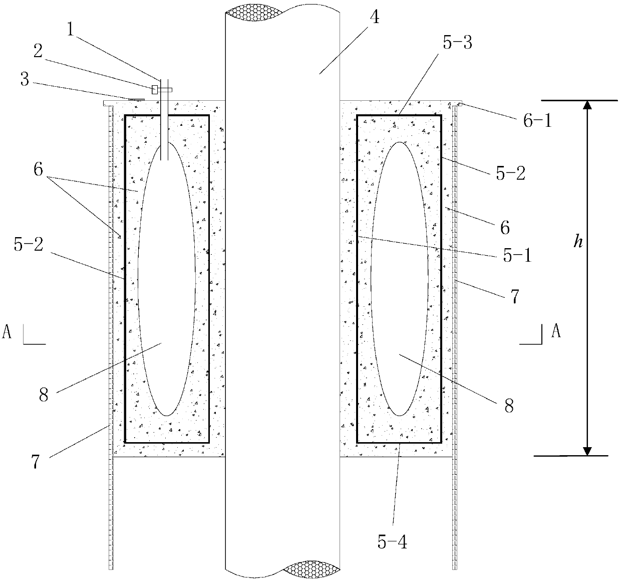
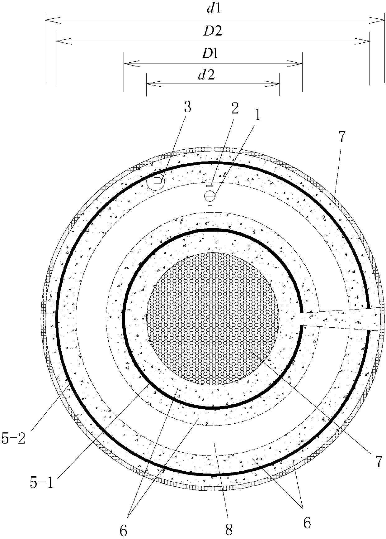
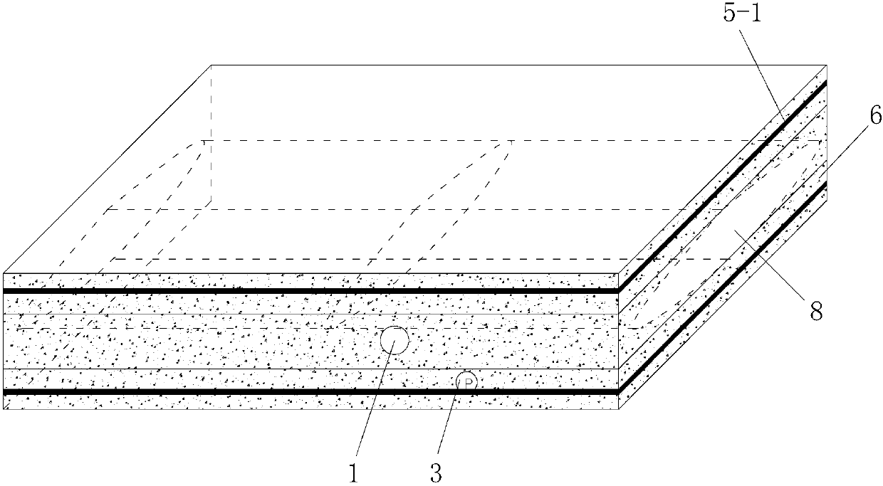
[0037] Such as figure 1 , figure 2 and image 3As shown, the present invention includes an annular rubber sheath 6 that is sleeved between the stay cable 4 and the cable sleeve 7, and the inner steel sheath 5-1, an annular oil bag 8 and The outer steel casing 5-2, the inner steel casing 5-1, the annular oil bag 8 and the outer steel casing 5-2 are arranged from inside to outside and all three are arranged coaxially with the annular rubber sheath 6 ; The inner steel casing 5-1 and the top of the outer steel casing 5-2 are connected by an upper annular steel plate 5-3, and the bottom of the inner steel casing 5-1 and the outer steel casing 5-2 They are connected by the lower annular steel plate 5-4, the upper annular steel plate 5-3 and the lower annular steel plate 5-4 are arranged in the annular rubber sheath 6, the inner steel sheath 5-1, the outer steel sheath The cylinder 5-2, the upper annular steel plate 5-3 and the lower annular steel plate 5-4 form a steel sheath; t...


PUM


Abstract

The invention discloses a cable-stayed built-in vibration damper, which comprises an annular rubber sheath set between the cable-stay and the cable sleeve, and an inner steel sheath and an annular oil bag are arranged in the annular rubber sheath and the outer steel casing, the inner steel casing, the annular oil bag and the outer steel casing are arranged from the inside to the outside and all three are arranged coaxially with the annular rubber sheath; the inner steel casing, the outer steel casing, and the upper ring The steel plate and the lower annular steel plate form a steel sheath; the annular oil bag is located in the steel sheath, and the annular rubber sheath is provided with an oil bag installation cavity for the installation of the annular oil bag; the annular rubber sheath is equipped with a oil injection pipe. The invention is simple in structure, reasonable in design, easy to manufacture and install, good in use effect, can be easily and quickly installed in the gap between the cable stay and the cable casing, has low requirements on the installation precision of the cable stay, and can be used with The stay cable and the cable casing are evenly contacted, the vibration damping effect is good, and it is economical and practical.

Description

technical field [0001] The invention relates to a vibration damping device, in particular to a built-in vibration damper for a stay cable. Background technique [0002] Cable-stayed cables are the main stress-bearing components of cable-stayed bridges, which have a direct and important impact on the structural safety and service life of cable-stayed bridges. The safety and durability of cable-stayed bridges depend to a large extent on the performance. Since the stay cables are arranged outside the beam body and are under high stress for a long time, the stay cables will inevitably vibrate under the action of wind, rain, snow, etc. The vibration of the stay cable will cause repeated deflection at the root of the stay cable, and the steel wire in the stay cable will generate additional flexural stress. The service life of the stay cables is shortened, and the continuous vibration of the stay cables will make people doubt the reliability and stability of the bridge. Therefore...

Claims


Application Information

Patent Timeline
Patent Type & Authority Patents(China)
IPC IPC(8): E01D19/16
CPCE01D19/16
Inventor 刘来君张筱雨杨懿杰陈冰洋郭洪超
Owner CHANGAN UNIV
Why Eureka
Try Eureka