Coke oven flue gas treatment structure

A technology of flue gas treatment and coke oven, which is applied in the direction of coke oven, climate change adaptation, climate sustainability, etc., can solve the problems of increased power consumption, smoke and dust escape, unsatisfactory results, etc., to achieve reduced consumption, wide range, The effect of improving the efficiency of flue gas collection and treatment

Inactive Publication Date: 2016-09-21
SICHUAN ANCHUANG ENVIRONMENTAL PROTECTION TECH CO LTD
View PDF0 Cites 2 Cited by
  • Summary
  • Abstract
  • Description
  • Claims
  • Application Information

AI Technical Summary

Problems solved by technology

The temperature of the coke discharge smoke is high, the instantaneous thermal buoyancy and the amount of dust are large, but the area ratio of the bucket-type dust collection hood between the top of the coke holding car and the top of the coke quenching car is very different, and the suction of the ground dust removal fan is mainly allocated to the coke quenching The bucket-type dust collection cover on the top of the carriage, and there is a gap between the coke-guiding grid-covered bucket-type dust collection cover and the small burner, so part of the smoke escapes from the small burner.
In order to improve the dust removal effect, some coking enterprises adopt the method of opening holes on the side plate of the bucket-type dust collection cover near the furnace body on the top of the coke guide grid and attaching a vehicle-mounted fan to assist dust collection. Some enterprises adopt the method of adjusting the dust removal fan of the ground station to run at high speed in advance The time parameter is used to pre-increase the suction force of the red coke in the initial grid entry stage; but the results are not satisfactory, and the power consumption is also increased

Method used


Image

  • Coke oven flue gas treatment structure

Examples


Embodiment 1

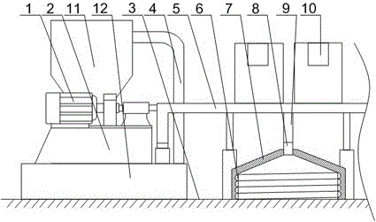
[0021] Such as figure 1 As shown, the present embodiment is provided with a support seat 2 on the base line 3 of the furnace top, on which the blower fan 1 and the dust collector 11 are fixed, and also includes a main air pipe 5, an ascending pipe 4, a temporary storage chamber 12 and multiple A gas collecting hood 7, the gas collecting hood 7 is covered on the outer side of two adjacent coke-side small burners, and one end of the main air pipe 5 is connected with the air suction port of the blower fan 1 and the temporary storage cavity 12 respectively, The other end of the trachea 5 communicates with a plurality of the gas collecting hoods 7 through the bronchus 9, one end of the rising pipe 4 communicates with the air inlet of the dust collector 11, and the other end of the rising pipe 4 communicates with the temporary storage cavity 12; the gas collecting hood 7 It is composed of interconnected collection section and refraction section. The collection section is cylindrical...


PUM


Abstract

The invention discloses a coke oven flue gas treatment structure. A support seat is disposed on an oven top base line, a fan and a dust remover are fixed on the support seat, the structure also comprises a main gas pipe, a riser pipe, a temporary storage cavity and a plurality of gas collecting hoods, one end of the main gas pipe is communicated with an exhaust opening of the fan and the temporary storage cavity respectively, the other end of the main gas pipe is communicated with a plurality of gas collecting hoods through branch pipes, one end of the riser pipe is communicated with a gas inlet of the dust remover, and the other end of the riser pipe is communicated with the temporary storage. Each gas collecting hood is composed of a collecting section and a refraction section that are connected to each other, the inner wall of the collecting section is provided with a spiral groove, the refraction section is cone-shaped, and the conical tip of the refraction section is communicated with a branch pipe end. During work, the plurality of gas collecting hoods concentratedly collect the flue gas dissipating from an oven's burner on the oven top base line simultaneously, and the collected flue gas enters the main gas pipe through the branch pipes, then enters a dust filter under the pull of the fan's wind force to undergo flue gas treatment, thus eradicating dissipation of oven top flue gas and avoiding environmental pollution.

Description

technical field [0001] The invention relates to the technical field of coking and environmental protection, in particular to a coke oven flue gas treatment structure. Background technique [0002] Coking is a multi-source pollution industry, and smoke and dust are the main pollutant fugitives in the coking production process. Modern chamber coke ovens are generally equipped with vehicle-mounted or ground station coal charging and coke discharge dust removal systems, of which the ground station dust removal system is widely used. The ground station type coke discharge dust removal system mainly uses hydraulic coupling or frequency conversion control fans to collect most of the smoke dust on the coke side through the collection cover set on the coke stop car and purifies it through the coke discharge dust collector. However, part of the smoke and dust still escapes from the small burner head on the coke side, which deteriorates the working environment. The coke discharge smo...

Claims


Application Information

Patent Timeline
Patent Type & Authority Applications(China)
IPC IPC(8): C10B43/00B01D46/02
CPCB01D46/02C10B43/00Y02A50/2351
Inventor 陈昱
Owner SICHUAN ANCHUANG ENVIRONMENTAL PROTECTION TECH CO LTD
Why Eureka
Try Eureka