Coke furnace top dust removal device

A technology of dust removal device and furnace roof, which is applied in coke ovens, smoke removal, combined devices, etc., can solve problems such as increased power consumption, smoke emission, and unsatisfactory results, and achieves elimination of emission, avoidance of smoke accumulation, and avoidance of The effect of polluting the environment

Inactive Publication Date: 2018-03-06
付建军
View PDF0 Cites 0 Cited by
  • Summary
  • Abstract
  • Description
  • Claims
  • Application Information

AI Technical Summary

Problems solved by technology

The temperature of the coke discharge smoke is high, the instantaneous thermal buoyancy and the amount of dust are large, but the area ratio of the bucket-type dust collection hood between the top of the coke holding car and the top of the coke quenching car is very different, and the suction of the ground dust removal fan is mainly allocated to the coke quenching The bucket-type dust collection cover on the top of the carriage, and there is a gap between the coke-guiding grid-covered bucket-type dust collection cover and the small burner, so part of the smoke escapes from the small burner.
In order to improve the dust removal effect, some coking enterprises adopt the method of opening holes on the side plate of the bucket-type dust collection cover near the furnace body on the top of the coke guide grid and attaching a vehicle-mounted fan to assist dust collection. Some enterprises adopt the method of adjusting the dust removal fan of the ground station to run at high speed in advance The time parameter is used to pre-increase the suction force of the red coke in the initial grid entry stage; but the results are not satisfactory, and the power consumption is also increased

Method used


Image

  • Coke furnace top dust removal device
  • Coke furnace top dust removal device
  • Coke furnace top dust removal device

Examples


Embodiment 1

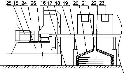
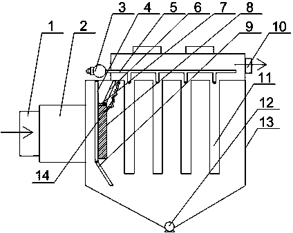
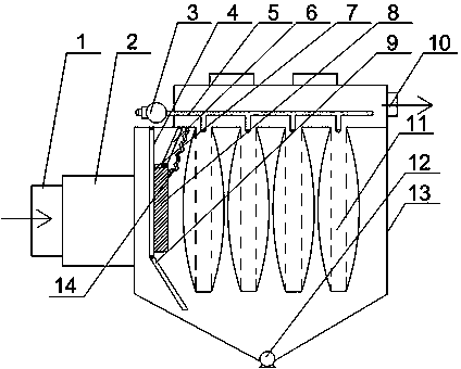
[0027] Such as Figure 1~Figure 3 As shown, the present embodiment is provided with a supporting base 15 on the base line 3 of the furnace roof, and the fan 25 and the dust collector 24 are fixed on the supporting base 15. A gas collecting hood 20, the gas collecting hood 20 is covered on the outer side of two adjacent coke-side small burners, one end of the main air pipe 18 communicates with the air suction port of the fan 25 and the temporary storage cavity 26 respectively, The other end of the trachea 18 communicates with a plurality of the gas collecting hoods 20 through the bronchus 9, one end of the rising pipe 17 communicates with the air inlet of the dust collector 24, and the other end of the rising pipe 17 communicates with the temporary storage cavity 26; the gas collecting hood 20 It is composed of a collection section and a refraction section connected to each other. The collection section is cylindrical and has a spiral groove 19 on its inner wall along its axis ...


PUM


Abstract

The invention discloses a coke furnace top dust removal device. A support seat is arranged on a furnace top base line, a draught fan and a dust collector are fixed on the support seat, a main gas pipeand a plurality of gas-collecting hoods are further included, the gas-collecting hoods cover the position right above outsides of two adjacent coke side small furnace heads, one end of the main gas pipe communicates with an exhaust inlet of the draught fan and a gas inlet of the dust collector respectively, and the other end of the main gas pipe communicates with the plurality of gas-collecting hoods through branch gas pipes; the gas-collecting hoods comprise collecting sections and refraction sections which are mutually connected, the collecting sections are provided with spiral grooves in axial directions in inner walls of the collecting sections, and the refraction sections are conical and provided with conical tips communicating with tail ends of the branch pipes. During work, the plurality of gas-collecting hoods concentrate and collect flue gas escaping from the small furnace heads on the furnace top base line, the collect flue gas enters the main gas pipe through the branch gaspipes and then enters a dirt catcher under the traction of wind power from the draught fan to be subjected to flue gas treatment, the furnace top flue gas is avoided from escape, and the pollution tothe environment is avoided.

Description

technical field [0001] The invention relates to the technical field of coking and environmental protection, in particular to a coke oven top dedusting device. Background technique [0002] Coking is a multi-source pollution industry, and smoke and dust are the main pollutant fugitives in the coking production process. Modern chamber coke ovens are generally equipped with vehicle-mounted or ground station coal charging and coke discharge dust removal systems, of which the ground station dust removal system is widely used. The ground station type coke discharge dust removal system mainly uses hydraulic coupling or frequency conversion control fans to collect most of the smoke dust on the coke side through the collection cover set on the coke stop car and purifies it through the coke discharge dust collector. However, part of the smoke and dust still escapes from the small burner head on the coke side, which deteriorates the working environment. The coke discharge smoke from ...

Claims


Application Information

Patent Timeline
Patent Type & Authority Applications(China)
IPC IPC(8): C10B43/00B01D50/00B08B15/02B08B15/04
CPCC10B43/00B08B15/02B08B15/04B01D50/20Y02P20/133
Inventor 付建军
Owner 付建军
Why Eureka
Try Eureka