
A method for generating a payload adaptation structure for a satellite system

A technology for adapting structures and satellite systems, which is applied to space navigation equipment, space navigation vehicles, space navigation equipment, etc., and can solve problems such as unrealized effects, low load-bearing mass ratio, and failure to exert composite structural performance.

Active Publication Date: 2019-02-12
BEIJING INST OF SPACECRAFT SYST ENG
View PDF3 Cites 0 Cited by
  • Summary
  • Abstract
  • Description
  • Claims
  • Application Information

AI Technical Summary

Problems solved by technology

[0005] (1) Most of these supporting structures are metal brackets - poor dimensional thermal stability and low load-bearing mass ratio;
[0006] (2) Existing composite supports mostly use quasi-isotropic laminates, which do not take advantage of the designable characteristics of composite structures. In addition, in terms of high stability design, many structures are more about ensuring the stability of one dimension, such as each This kind of rod, beam and other structures only ensure the minimum dimensional deformation in one direction of the length, and do not achieve the same effect in the other two dimensions
However, with the improvement of user requirements for observation accuracy, especially for cameras and payloads with high requirements for pointing accuracy, these loads have high requirements for on-orbit pointing accuracy, and they need to be kept stable for a long time in orbit. However, the existing technology No relevant information has been found to achieve the above purpose

Method used


Image

  • A method for generating a payload adaptation structure for a satellite system
  • A method for generating a payload adaptation structure for a satellite system
  • A method for generating a payload adaptation structure for a satellite system

Examples


Embodiment Construction

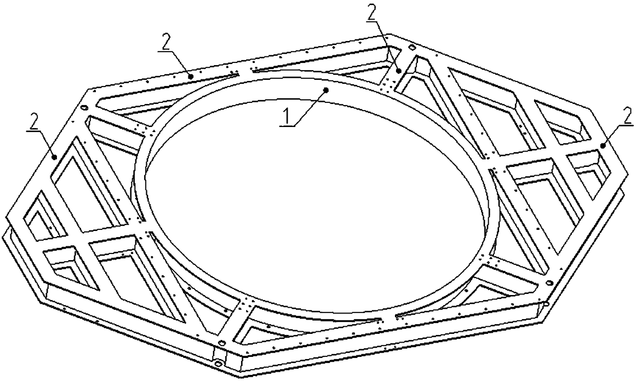
[0025] In the following, the present invention will be further elaborated by taking the load adaptation structure for carrying cameras and star sensors on a certain satellite as an example in conjunction with the accompanying drawings.

[0026] The load-bearing and thermal stability design of the load-adapted structure is realized by combining the configuration with the lay-up design:

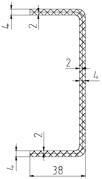
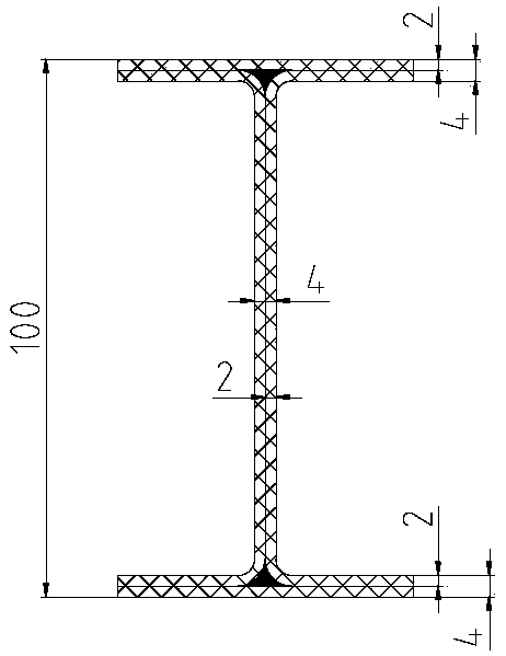
[0027] The camera carrying area is located in the attached figure 1 The middle annular part 1 shown is a "C-shaped beam" structure, and holes are opened on the wing plate of the beam to provide a connection interface; the bearing area and structural connection points of the star sensor are all located in the "I-shaped beam" around the round frame 2, as attached figure 1 As shown, holes are made on the flanges of the beams to provide connection interfaces; through the method of finite element analysis, the simulation analysis is carried out for the two-dimensional dimensional stability in the p...


PUM


Abstract

A method for generating a load adaption structure for a satellite system comprises the first step of laying webs, i.e., a plurality of C-shaped webs are spliced into one or more sealed areas; the second step of generating arc edges of the sealed areas of the adaption structure by laying C-shaped webs on the corresponding C-shaped webs in the same direction, and generating straight edges of the sealed areas of the adaption structure by splicing C-shaped webs on the corresponding C-shaped webs in the reverse direction; and the third step of assembling the sealed areas into the shape of the adaption structure, and laying wing plates on all the straight edges and arc edges of the adaption structure. According to the third step, the wing plates in a bearing area are continuously laid in multiple layers in different directions, and the wing plates in a non-bearing area are provided with breaking points which are located on the same layers and in different directions. By means of the method, the size stability and the bearing mass ratio of the load adaption structure after long-time use in orbit are improved, and mounting foundation faces are provided for large loads such as cameras.

Description

technical field [0001] The invention belongs to the field of spacecraft structures, in particular to a method for generating a load adaptation structure for a satellite system. Background technique [0002] When the spacecraft is in orbit, it is in a high vacuum, alternating cold and heat environment, and is damaged and destroyed by various space factors such as cosmic rays, solar radiation, high-energy particles, plasma, atomic oxygen, etc., which seriously threatens the on-orbit spaceflight. device reliability and security. Space environmental factors cause changes, damage, and even destruction of spacecraft material properties in different ways, resulting in changes in the basic properties of materials such as mechanical properties and thermal expansion coefficients, which in turn affect the performance of high-precision loads on some stars, such as high-resolution earth observation satellite cameras. The imaging accuracy of the spacecraft is even a serious threat to the...

Claims


Application Information

Patent Timeline
Patent Type & Authority Patents(China)
IPC IPC(8): B64G1/22
CPCB64G1/22
Inventor 白刚罗文波陈海峰徐伟丽高峰田鑫刘国青
Owner BEIJING INST OF SPACECRAFT SYST ENG
Learn More