
Real-time motor control device for hitting speed of die-casing machine

A real-time control, die-casting machine technology, applied in the field of control devices, can solve the problems of large starting force, accelerated component damage, long reaction time, etc., to achieve the effects of precise repetitive control, precise real-time control, and reduced reaction time

Inactive Publication Date: 2016-09-21
ZHONGSHAN DEGONG MACHINERY TECH CO LTD
View PDF5 Cites 1 Cited by
  • Summary
  • Abstract
  • Description
  • Claims
  • Application Information

AI Technical Summary

Problems solved by technology

[0003] As one of the components for controlling the feeding speed of the die-casting machine, the cartridge valve cover is set on the oil circuit board at the position of the cartridge valve of the die-casting machine. Soaked in the die-casting machine oil, when the bearing seat converts the rotary motion into the linear motion of the ejector rod, one side of the piston set on the ejector rod is soaked in the die-casting machine oil, and the cavity where the other end is located is air. During the movement, due to the unbalanced pressure at both ends during the movement, when the user is in the process of feeding, when the rotating bearing seat drives the ejector rod, because of this problem, a huge thrust will be generated when the cartridge valve is 300kg to more than 10 tons. friction, resulting in large starting force, long response time, long-term use and even accelerated component damage
[0004] In addition, in the past, the device used to control the rotation of the bearing seat was driven by manual rotation of the hand wheel. Using the manual hand wheel method would make the control of the feeding speed inaccurate and cause large errors, which could not realize intelligent and automated production. At the same time, manual screwing Action does not ensure reaction time at certain times
[0005] However, the cost of control devices using hydraulic electric proportional valves or servo adjustments or numerical control regulators is high, and the repeatability of injection products is low, so precise real-time control cannot be performed.

Method used


Image

  • Real-time motor control device for hitting speed of die-casing machine
  • Real-time motor control device for hitting speed of die-casing machine
  • Real-time motor control device for hitting speed of die-casing machine

Examples


Embodiment Construction

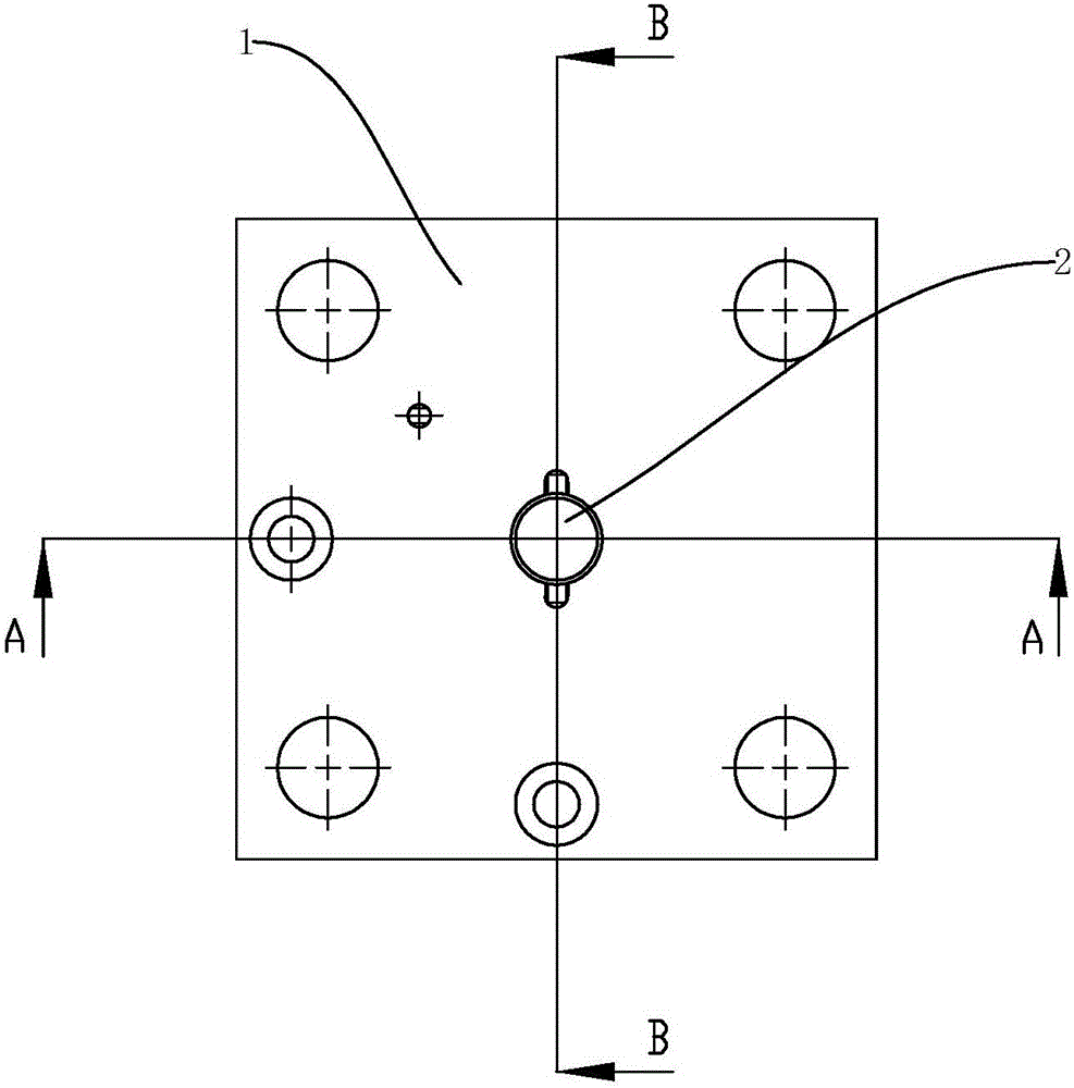
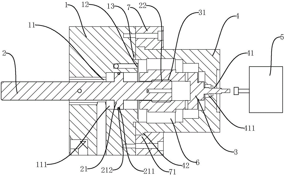
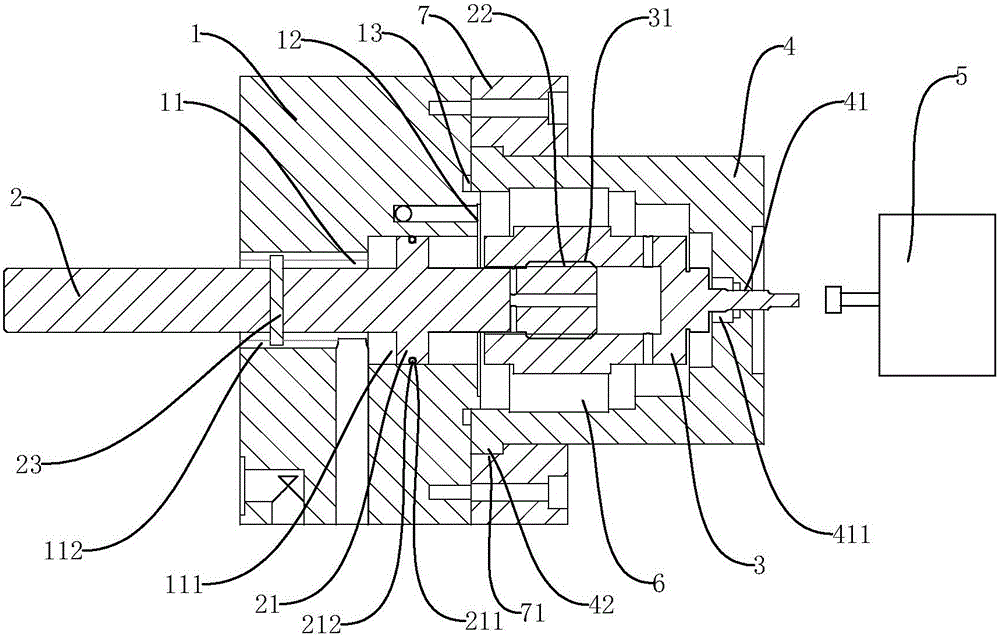
[0022] Such as figure 1 , figure 2 As shown, the control device of the present invention is used to control the feeding speed of the die-casting machine. The output end is connected to the bearing seat 3 of the input end of the ejector rod 2 and the bearing cover 4 for fixing the bearing seat 3. In this design, the control motor 5 is selected to realize automatic control. The bearing cover 4 is provided with a first through hole 41, and the bearing seat 3 The output end passes through the first through hole 41 to connect the bearing of the control motor 5, and the bearing cover 4 is in sealing connection with the cartridge valve cover 1.

[0023] The control device converts the rotational motion of the bearing seat 3 into the linear motion of the ejector rod 2 through the cooperative connection between the bearing seat 3 and the ejector rod 2, and the linearly moving ejector rod adjusts the feeding speed of the die-casting machine. The specific structure is as follows:

[0...


PUM


Abstract

The invention discloses a real-time motor control device for the hitting speed of a die-casting machine. The real-time motor control device for the hitting speed of the die-casting machine comprises a cartridge valve deck, an ejector rod, a bearing seat, a bearing cap and a control motor, wherein the cartridge valve deck is arranged on an oil circuit board in the position of a cartridge valve of the die-casting machine, the output end of the ejector rod is connected with a hitting component of the die-casting machine, the output end of the bearing seat is connected with the input end of the ejector rod, the bearing cap is used for fixing the bearing seat, and the control motor is used for controlling the hitting speed of the die-casting machine. An inner cavity is formed in the cartridge valve deck and the bearing cap. An oil pipe is arranged in the cartridge valve deck, one end of the oil pipe is connected with a pressure oil tank in the cartridge valve, and the other end of the oil pipe is connected with the inner cavity. The oil pipe is used for allowing pressure oil to be guided therein, so that the pressure of the two ends of a piston arranged on the ejector rod is balanced. Through the design, the bearing seat can be rotated easily, and overload of the control motor is prevented; meanwhile, back-and-forth repeated control is more accurate, stress during starting is reduced, the response time is shortened accordingly, and accurate real-time control can be achieved through the cooperation of the real-time motor control device and a switching mechanism.

Description

technical field [0001] The invention relates to a control device, in particular to a real-time control device of a motor for feeding speed of a die-casting machine. Background technique [0002] Die-casting machine is a commonly used machine in industrial manufacturing. With the increasingly complex parts being cast, the control requirements for the internal components of the die-casting machine are correspondingly increased. Here, we will improve the components that control the feeding speed of the die-casting machine. [0003] As one of the components for controlling the feeding speed of the die-casting machine, the cartridge valve cover is set on the oil circuit board at the position of the cartridge valve of the die-casting machine. Soaked in the die-casting machine oil, when the bearing seat converts the rotary motion into the linear motion of the ejector rod, one side of the piston set on the ejector rod is soaked in the die-casting machine oil, and the cavity where th...

Claims


Application Information

Patent Timeline
IPC IPC(8): B22D17/32
CPCB22D17/32
Inventor 郭浩标
Owner ZHONGSHAN DEGONG MACHINERY TECH CO LTD
Learn More