Low-construction trolley for wire rope hoist

A hoist and wire rope technology, which is applied to motor vehicles, traveling mechanisms, clockwork mechanisms, etc., can solve the problems of hoisting rope wear, trolley bumping movement, wear and scratches, etc., and achieve the reduction of bending moment and drift reduction Effect

Active Publication Date: 2016-09-14
KONECRANES GLOBAL
View PDF8 Cites 7 Cited by
  • Summary
  • Abstract
  • Description
  • Claims
  • Application Information

AI Technical Summary

Problems solved by technology

However, such asymmetrical and long lever arms with respect to the main support cause additional twisting of the rope system relative to the vertical axis when lifting and lowering loads, and thus cause harmful Large bending moments and the resulting additional stresses also cause additional stresses on the main supports
Uneven loading causes premature wear and scuffing of the support wheels and / or guide surfaces on beams or rails that the main support may have, causing jerky motion of the trolley
[0004] In addition, as the fixing point of the hoisting rope to the drum is usually on the side of the trolley where the fixing point of the hoisting rope to the frame of the trolley is also located, the part of the rope system that creates the fixed fixing point may, when the lifting member is being lowered, Hitting the part of the rope system coming from the drum, which can cause wear and damage to the hoisting rope

Method used


Image

  • Low-construction trolley for wire rope hoist
  • Low-construction trolley for wire rope hoist
  • Low-construction trolley for wire rope hoist

Examples


Embodiment Construction

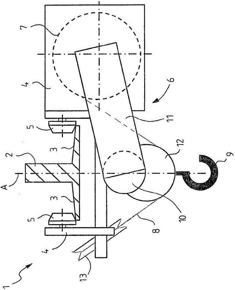
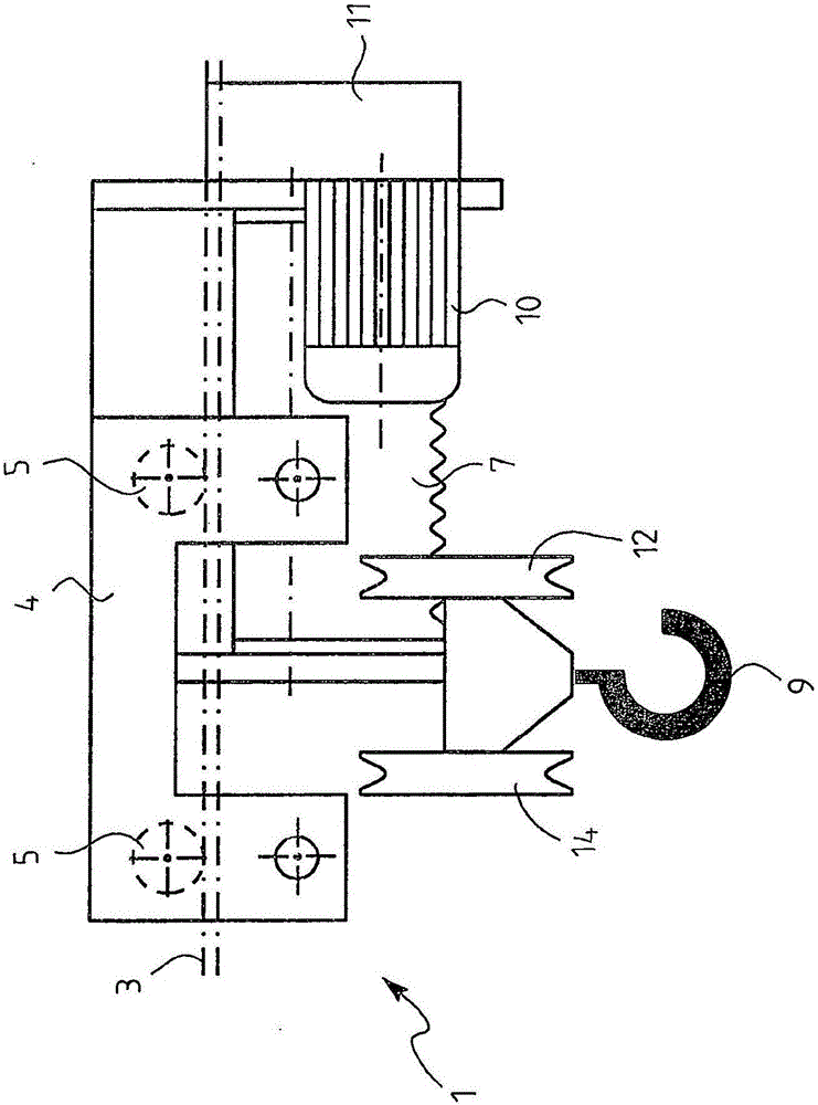
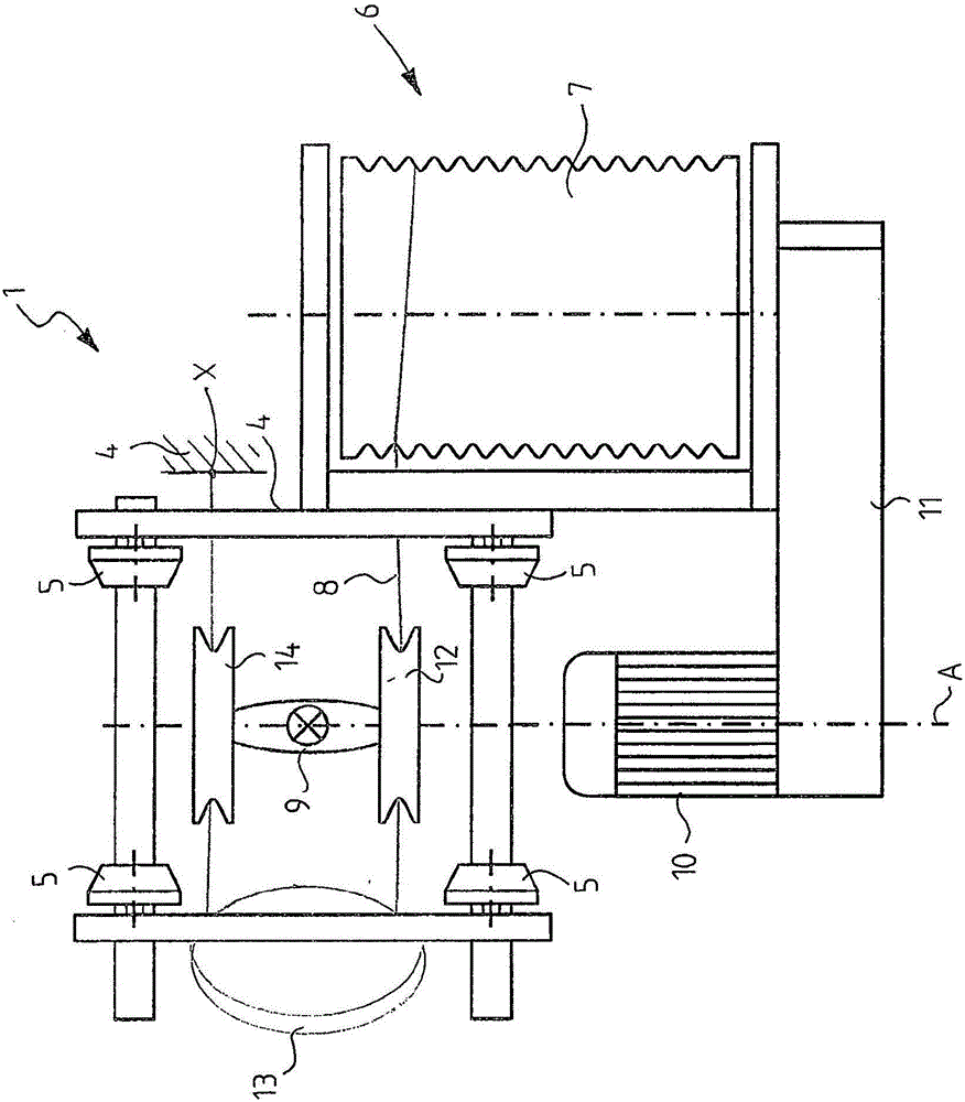
[0028] With reference to the attached drawings, first of all reference is made to Figures 1 to 3 , like here, it can be seen that a low-structure trolley 1 for a wire rope hoist is arranged to run along a horizontal beam or the lower flange 3 of a guide rail 2 . The guide rail 2 usually establishes the main support of the bridge crane or is included in the bridge crane as the lowest part of the main support of the bridge crane.

[0029] The trolley 1 is shown by means of a simplified functional diagram showing only the components required for the understanding of the invention.

[0030] The trolley 1 includes a trolley frame 4 , support wheels 5 and a lifting mechanism 6 .

[0031] Support wheels 5 are attached to the trolley frame 4 and are arranged to run on the upper surface of the lower flange 3 of the guide rail 2 on both longitudinal edges of the guide rail 2, and at least some of said support wheels are to make the platform Car 1 moves the driven wheels. The actuato...


PUM


Abstract

The invention relates to a low-construction hoist (1) for a wire rope hoist, arranged to move along a lower flange (3) of a horizontal beam or rail (2), whereby the trolley (1) comprises a trolley frame (4); bearing wheels (5), which are fixed to the trolley body and arranged to move on the upper surface of the lower flange (3) of the rail, a hoisting mechanism (6) comprising a rope drum (7) for a hoisting rope (8), a hoisting member (9) in cooperation with the hoisting rope for hoisting a load, and a hoisting motor (10) for driving the rope drum; whereby the rope drum is supported to a first side of the trolley frame so that the axle of the rope drum is parallel to the rail, and the hoisting member is arranged to move under the rail; whereby the hoisting rope (8) is led from the rope drum (7) to a fixing point (X; Z) in the trolley frame (4) through at least a rope pulley arrangement (12, 14) of the hoisting member (9), whereby the fixing point (X) of the hoisting rope (8) to the trolley frame (4) is located in the longitudinal direction of the trolley (1) outside the end of the rope drum (7), or outside the vertical plane which is transverse in relation to the rail or beam (2) and passing through the end of the rope drum.

Description

technical field [0001] A low-structure trolley for a wire rope hoist, the low-structure trolley is arranged to travel along the lower flange of a horizontal beam or guide rail, wherein the low-structure trolley comprises: a trolley frame; support wheels, the Support wheels are attached to the trolley frame and are arranged to run on the upper surface of the beam or the lower flange of the guide rail, and some of the support wheels are driven wheels for moving the trolley; a lifting mechanism, the lifting mechanism comprising a rope drum for the hoist rope, a lifting member cooperating with the hoist rope to lift the load, and a hoist motor for driving the rope drum; wherein the rope drum is supported to a first side of the trolley frame such that the drum The axis of the rope drum is parallel to the beam or guide rail, and the lifting member is arranged to move under the beam or guide rail; wherein the lifting rope is guided from the rope drum through at least one rope pulley ...

Claims


Application Information

Patent Timeline
Patent Type & Authority Applications(China)
IPC IPC(8): B66C9/14B66C11/06B61B3/00B60M1/28
CPCB66C11/06B66C9/14B66C9/10B66C11/16B66C19/00B66D1/12B66D1/14B66D1/36
Inventor T·林德伯格H·科科
Owner KONECRANES GLOBAL
Why Eureka
Try Eureka