
Tibia remote end fixing device

A fixation device and distal technology, applied in fixers, internal bone synthesis, medical science, etc., can solve problems such as nail body deformation, deformation, bone plate misalignment, etc.

Inactive Publication Date: 2016-09-14
A PLUS BIOTECH
View PDF6 Cites 4 Cited by
  • Summary
  • Abstract
  • Description
  • Claims
  • Application Information

AI Technical Summary

Problems solved by technology

[0003] At present, for distal tibial fractures, external fixator (External Fixator) or bone plate (BonePlate) fixation device can be used. The fixation device is placed on the distal tibial fracture through surgery, and the external fixation device is fixed by screw. The fixator is combined with the tibia, or the bone plate is attached to the tibia and then fixed with bone nails. However, the external fixator has several disadvantages compared with the bone plate: (1) The external fixator has a large volume and must be placed on the patient's body This will cause the patient's postoperative appearance to be less beautiful and will limit the patient's movement; (2) external fixators are only suitable for specific fracture situations; (3) according to the research of Lewallen et al. (Comparison of the effects of compression plates and external fixators on early bone-healing, c66J.Bone.Joint Surg.Am.1084,1984.), the tibia after healing with external fixators has poor bone regeneration and has more holes
Third, the currently known tibial bone plate is to fix the bone nail to the screw hole of the bone plate, so that the nail cap (Cap) of the bone nail is located on the bone plate, and the nail body of the bone nail penetrates into the tibia. However, the tibia The distal end bears most of the weight of the human body. If only the nail cap of the bone nail is fixed on the bone plate to form a cantilever beam structure, the force generated at the ankle joint will deform the nail body due to the principle of leverage, and cause The plate is at risk of misalignment or deformation

Method used


Image

  • Tibia remote end fixing device
  • Tibia remote end fixing device
  • Tibia remote end fixing device

Examples


Embodiment Construction

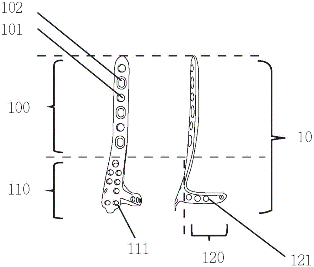
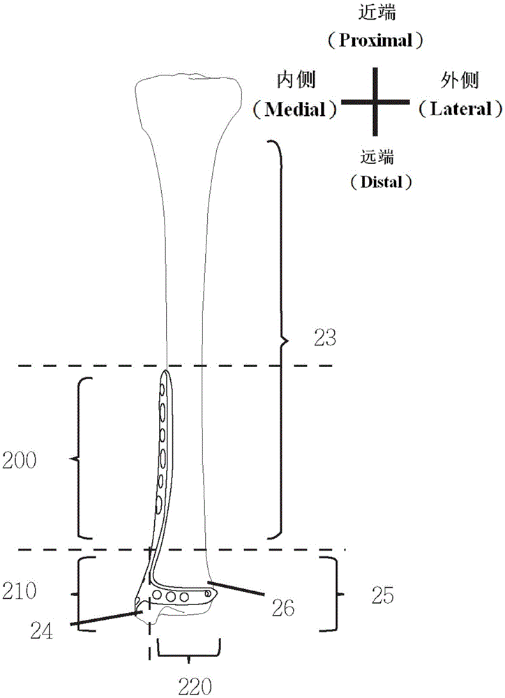
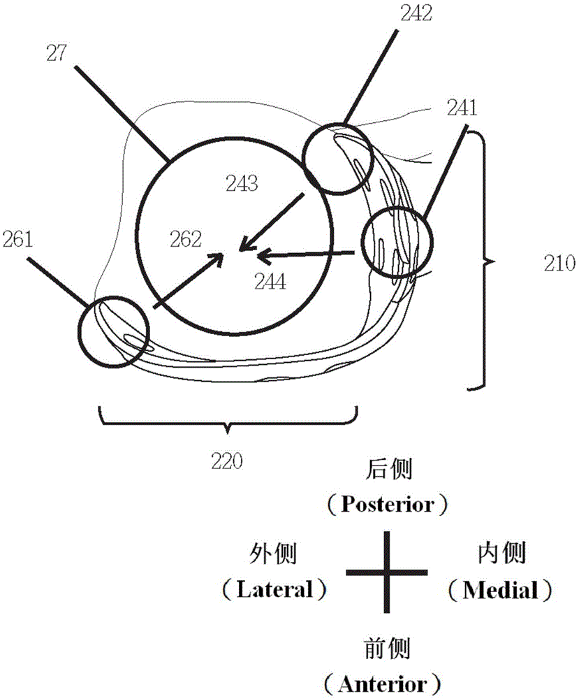
[0042] The distal tibia fixation device 10 of the first embodiment of the present invention comprises a backbone fixation part 100, a medial malleolus fixation part 110 and a fin part 120, see figure 1 . see also figure 2The backbone fixing part 200 is a long and narrow fixing piece, which can be attached to the tibial shaft 23 (Tibial Shaft) in parallel during the operation, or further, the backbone fixing part 200 can be attached inside the tibial shaft 23 On the surface (Medial Surface). There is a medial malleolus fixation part 210 at the distal end of the diaphysis fixation part 200, which can cover the patient's distal tibia 25 and its medial malleolus 24 (Medial Malleolus). The medial malleolus fixation part 210 has a fin 220 along the front side of the tibia (Anterior), along the front edge of the distal tibia 25 (or on the front side along the direction of the distal tibial epiphysis and the subchondral bone between the joints) from the medial side. Cover the area...


PUM


Abstract

The invention discloses a tibia remote end fixing device including a bone fixing part capable of adhering to the tibia bone; a malleolus medialis fixing part extending from the bone fixing part in the tibia remote end direction and capable of adhering to the malleolus medialis; a fin part extending to a tibiofibula remote end joint from the malleolus medialis fixing part in the front direction of the tibia horizontally, wherein an arbitrary one of the bone fixing part, the malleolus medialis fixing part and the fin part is provided with at least one screw hole and a fixing bone nail and the malleolus medialis fixing part and the fin part can be embedded into the surface of the tibia remote end.

Description

technical field [0001] The present invention is a tibial distal fixation device, which is a bone plate, which is used for fixing the bone at the tibial distal end in ankle fracture. Background technique [0002] The tibia is located at the lower leg of the human body, and its distal end is located at the ankle of the human body. Traumatic fractures of the distal tibia can be divided into articular fractures, metaphyseal fractures, and diaphyseal fractures according to the fracture site. Fractures can be divided into Simple Fracture, Wedge Fracture, and Complex Fracture. In addition to bone fragmentation, the above fractures may be accompanied by dislocation of bone fragments. [0003] At present, for distal tibial fractures, external fixator (External Fixator) or bone plate (BonePlate) fixation device can be used. The fixation device is placed on the distal tibial fracture through surgery, and the external fixation device is fixed by screw. The fixator is combined with th...

Claims


Application Information

Patent Timeline
IPC IPC(8): A61B17/80A61B17/86
CPCA61B17/8061A61B17/86A61B2017/564
Inventor 朱家宏黄胜隆廖健雄
Owner A PLUS BIOTECH
Learn More