
Method for measuring efficiency of photovoltaic power station system

A photovoltaic power station and photovoltaic panel technology, which is applied in the monitoring of photovoltaic systems, photovoltaic power generation, photovoltaic modules, etc., can solve the problems of inability to truly reflect the radiation amount of photovoltaic panels, large errors, and inconvenient calibration

Active Publication Date: 2016-09-07
何旭
View PDF3 Cites 31 Cited by
  • Summary
  • Abstract
  • Description
  • Claims
  • Application Information

AI Technical Summary

Problems solved by technology

[0002] At present, most of the pyranometers in our country are thermoelectric. The pyranometer has a wide spectral range, generally roughly from 280nm to 3000nm in the full spectrum of the sun. The working range of solar cells is 400nm to 1100nm. The spectral range collected by the pyranometer is much larger than the working range spectrum of the solar cell, so the thermoelectric pyranometer cannot truly reflect the radiation received by the photovoltaic cell panel
Traditional irradiance meters do not take into account the influence of temperature on solar panel power generation, resulting in inaccurate PR values ​​and large errors, imported high-precision irradiance instruments are expensive, and domestic instruments have low accuracy
Due to the different materials of the internal components of the irradiance, the attenuation of the internal photosensitive element and the influence of environmental factors cannot be calculated, and the calibration is inconvenient

Method used

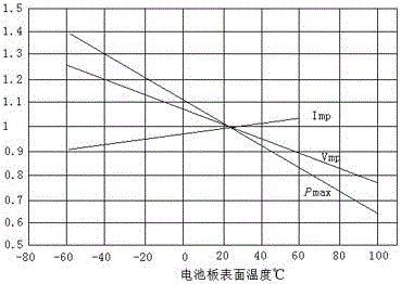
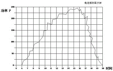

Image

  • Method for measuring efficiency of photovoltaic power station system
  • Method for measuring efficiency of photovoltaic power station system
  • Method for measuring efficiency of photovoltaic power station system

Examples


Embodiment 1

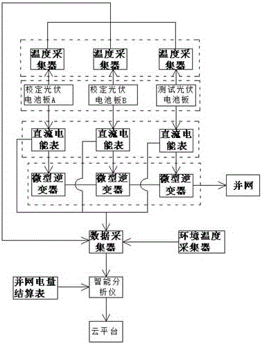
[0100] Embodiment 1, a method for measuring the performance of a photovoltaic power station system, is characterized in that: sunlight irradiates a photovoltaic cell panel, and the photovoltaic cell panel is a calibration photovoltaic panel A, a calibration photovoltaic panel B and a test photovoltaic panel, and the photovoltaic cell The DC current and voltage generated by the board are respectively converted into AC by the micro-inverter and then connected to the grid. The DC side of the micro-inverter is connected to the DC meter, and the DC meter is also connected to the data collector through the data line. The data collector is also connected to the Calibrate photovoltaic panel A, calibrate photovoltaic panel B and test the temperature collector set behind the photovoltaic panel, the temperature of the photovoltaic panel is transmitted to the data collector through the temperature collector, and the data collector is also connected to the ambient temperature collector conn...

Embodiment 2

[0106] Embodiment 2, a method for measuring the effectiveness of a photovoltaic power station system, is characterized in that: the photovoltaic panel is irradiated by sunlight, and the photovoltaic panel generates DC current and voltage, which are respectively converted into alternating current by a micro-inverter and then connected to the grid, and the micro-inverter The DC side is connected to the DC energy meter, and the DC energy meter is connected to the data collector through the data line, and the data collector is also connected to the calibration photovoltaic panel A, the calibration photovoltaic panel B and the temperature collector set behind the test photovoltaic panel. The temperature of the photovoltaic panel is transmitted to the data collector through the temperature collector, and the data collector is also connected to the ambient temperature collector. The data collection server transmits the collected data to the intelligent analyzer on the PC for intelligen...

Embodiment 3

[0113] Embodiment 3, a method for measuring the efficiency of a photovoltaic power station system, is characterized in that: the sunlight irradiates the photovoltaic cell panel, and the photovoltaic cell panel generates DC current and voltage respectively through the micro-inverter and converts it into alternating current and then connects to the grid, and the micro-inverter The DC side is connected to the DC energy meter, and the DC energy meter is connected to the data collector through the data line, and the data collector is also connected to the calibration photovoltaic panel A, the calibration photovoltaic panel B and the temperature collector set behind the test photovoltaic panel. The temperature of the photovoltaic panel is transmitted to the data collector through the temperature collector, and the data collector is also connected to the ambient temperature collector. The data collection server transmits the collected data to the intelligent analyzer on the PC for inte...


PUM


Abstract

The invention discloses a method for measuring the efficiency of a photovoltaic power station system, and relates to the field of photovoltaic power generation equipment detection. The system comprises a photovoltaic cell panel, a miniature inverter, a DC meter, a data collector, a temperature collector, an intelligent analyzer (a PC), and a cloud platform part. The beneficial effects of the invention are that the detected photovoltaic cell panel is smaller in irradiance receiving error, and is convenient to correct; the method can calculate a PR value, and the PR value is more suitable for the basic condition of the power station; the method can achieve the correction and testing of the attenuation power of an online working photovoltaic cell panel under the conditions of the same irradiance and temperature, and saves time and labor; the method can carry out the intelligent analysis and comparison of the power of a clean photovoltaic cell panel and a normal photovoltaic cell panel under the conditions of the same irradiance and temperature, calculates the impact on the photovoltaic cell panel from dust sheltering, determines the optimal washing time, and carries the accumulative analysis of the impact on the photovoltaic panel power generation from environment temperature and the temperature of a photovoltaic back plate through comparing the environment temperature with the temperature of the photovoltaic back plate.

Description

1. Technical field [0001] The invention relates to the field of detection of photovoltaic power generation equipment, in particular to a method for measuring the effectiveness of a photovoltaic power station system. 2. Background technology [0002] At present, most of the pyranometers in our country are thermoelectric. The pyranometer has a wide spectral range, generally roughly from 280nm to 3000nm in the full spectrum of the sun. The working range of solar cells is 400nm to 1100nm. The spectral range collected by the pyranometer is much larger than the working range spectrum of the solar cell, which makes the thermoelectric pyranometer unable to truly reflect the radiation received by the photovoltaic cell panel. Traditional irradiance meters do not take into account the influence of temperature on solar panel power generation, resulting in inaccurate PR values ​​and large errors. Imported high-precision irradiance instruments are expensive, and domestic instruments have ...

Claims


Application Information

Patent Timeline
Patent Type & Authority Applications(China)
IPC IPC(8): H02S50/15
CPCH02S50/15Y02E10/50
Inventor 何旭
Owner 何旭
Learn More