
Practical novel intelligent alternating-current power-grid power-saving device

A technology of AC power grid and power saving device, which is applied in the direction of AC network voltage adjustment, can solve the problems of waste, power waste, and the inability of AC stabilized power supply to solve waste, etc., and achieves the effect of improving power factor and reducing three-phase unbalance.

Inactive Publication Date: 2016-09-07
STATE GRID SHANDONG ELECTRIC POWER CO YUNCHENG POWER SUPPLY CO
View PDF3 Cites 0 Cited by
  • Summary
  • Abstract
  • Description
  • Claims
  • Application Information

AI Technical Summary

Problems solved by technology

[0002] At present, the tap terminals of most user transformers are debugged and fixed at one time according to the maximum design capacity of the power grid, which cannot solve the problem of energy waste caused by large changes in the remote load current of the power grid
In fact, in those places that are close to power plants or substations, the "umbrella effect" phenomenon makes most electrical appliances receive a power supply voltage much higher than their rated voltage, making them in a state of overvoltage operation for a long time In addition, most high-voltage and high-power motors are running, especially in the process of dragging mechanical loads of low-density media (such as fans, liquid pumps, etc.), often because they cannot be used at any time according to demand. Reduce that part of the unnecessary output power, resulting in a large amount of waste of electric energy over time
Under such circumstances, the AC regulated power supply cannot solve the problem of waste (energy saving)

Method used


Image

  • Practical novel intelligent alternating-current power-grid power-saving device
  • Practical novel intelligent alternating-current power-grid power-saving device

Examples


Embodiment

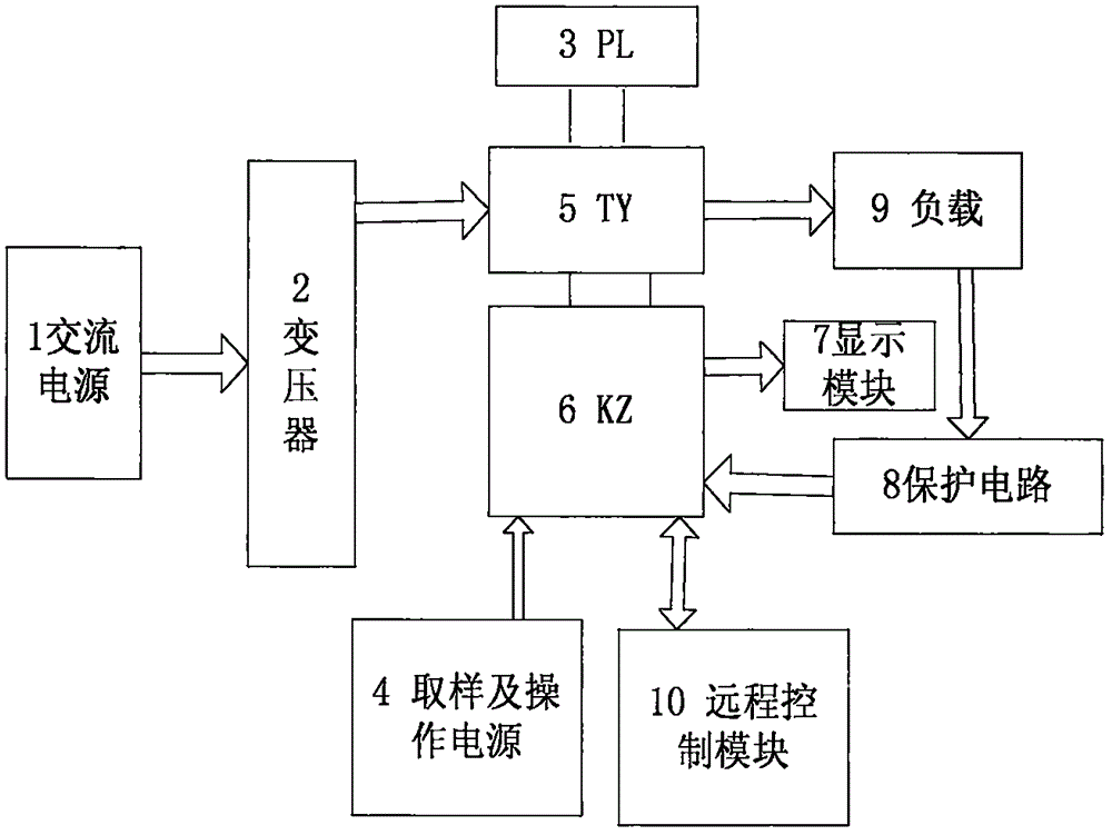
[0013] see figure 1 with figure 2 , the present invention provides a technical solution: a practical new intelligent AC power saving device, including AC power supply 1, transformer 2, sampling and operating power supply 4, PL automatic bypass unit 3, TY non-contact voltage regulation unit 5 , control unit KZ6, display module 7, protection circuit 8, load 9 and remote control module 10, the transformer 2 sends the AC power supply 1 to the TY non-contact voltage regulating unit 5 after performing voltage matching transformation, and the TY non-contact The point voltage regulating unit 5 is controlled on and off by the PL automatic bypass unit 3, the KZ control unit 6 is powered by the sampling and operating power supply 4, and the KZ control unit 6 obtains the voltage and current sample signal from the TY non-contact voltage regulating unit 5 , displayed by the display module 7 after analysis and processing, the protection circuit 8 samples the output of the load 9, and sends...


PUM


Abstract

The invention discloses a practical novel intelligent alternating-current power-grid power-saving device, comprising an alternating-current power source, a transformer, a sampling and operating power source, a PL automatic bypass unit, a TY contactless voltage-regulating unit, a control unit KZ, a display module, a protection circuit, a load and a remote control module. By means of the transformer, voltage of the alternating-current power source is matched and converted and then is sent to the TY contactless voltage-regulating unit. The on / off state of the TY contactless voltage-regulating unit is controlled by the PL automatic bypass unit. Power is supplied to the KZ control unit by the sampling and operating power source. Voltage current sample signals are obtained by the KZ control unit from the TY contactless voltage-regulating unit, are analyzed and processed, and then are displayed by the display module. An output end of the load is sampled by the protection circuit and sample signals are sent to the KZ control unit. The remote control module is connected onto the KZ control unit. With a simple structure, the practical novel intelligent alternating-current power-grid power-saving device of the invention achieves high safety, good energy-saving effect and high practicability and economical efficiency.

Description

technical field [0001] The invention relates to the application field of alternating current, in particular to a practical novel intelligent alternating current power saving device. Background technique [0002] At present, the tap terminals of most user transformers are debugged and fixed at one time according to the maximum design capacity of the power grid, which cannot solve the problem of power waste caused by large changes in the remote load current of the power grid. In fact, in those places that are close to power plants or substations, the "umbrella effect" phenomenon makes most electrical appliances receive a power supply voltage much higher than their rated voltage, making them in a state of overvoltage operation for a long time In addition, most high-voltage and high-power motors are running, especially in the process of dragging mechanical loads of low-density media (such as fans, liquid pumps, etc.), often because they cannot be used at any time according to de...

Claims


Application Information

Patent Timeline
Patent Type & Authority Applications(China)
IPC IPC(8): H02J3/12
CPCH02J3/12
Inventor 司志强刘冰王斌刘峰赵修涛彭永强季东升刘加涛李玉振李吉峰赵西良魏同起张鲁江
Owner STATE GRID SHANDONG ELECTRIC POWER CO YUNCHENG POWER SUPPLY CO
Learn More