
A pneumatic high pressure switch

A pneumatic high-voltage switch technology, which is applied to electric switches, power devices inside switches, electrical components, etc., can solve problems such as workers' dangers, and achieve reliable electrical contact surfaces, high pressure per unit area, and good electrical conductivity.

Inactive Publication Date: 2017-11-14
大唐阳城发电有限责任公司
View PDF3 Cites 0 Cited by
  • Summary
  • Abstract
  • Description
  • Claims
  • Application Information

AI Technical Summary

Problems solved by technology

[0002] High-voltage switch is one of the electrical components that factories often need to use. Most of the conventional high-voltage switches are manually operated, which is dangerous for workers who often use them. Therefore, there is an urgent need for a high-voltage switch that can be directly operated without hands.

Method used


Image

  • A pneumatic high pressure switch
  • A pneumatic high pressure switch
  • A pneumatic high pressure switch

Examples


Embodiment

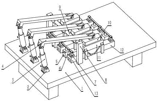
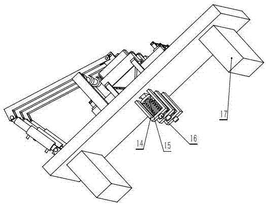
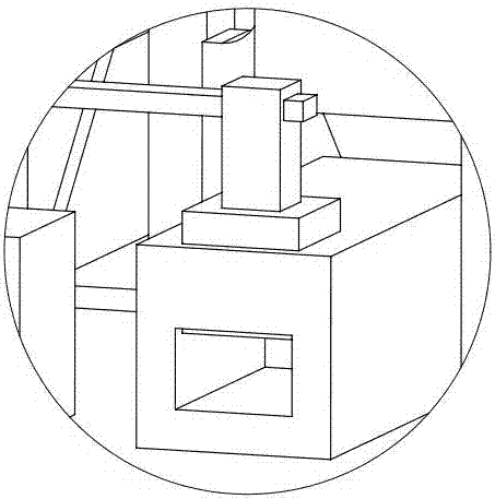
[0017] Such as figure 1 , figure 2 , image 3 , Figure 4 As shown, a pneumatic high-voltage switch includes a base plate 1, a hinge support 2, a first cylinder 3, a lever 4, a second cylinder 5, a cross bar 6, a pressure block 7, a bracket 8, a support shaft 9, and a V-shaped conductive block. 10. Guide frame 11, input terminal 12, output terminal 13, fixed frame 14, compression spring 15, thimble 16, characterized in that: the bottom plate 1 is a rectangular insulating plate, and a rectangular slot, three input terminals 12 and three output terminals 13 are arranged on both sides of the rectangular slot, and the end of the input terminal 12 and output terminal 13 close to the rectangular slot is processed into a chamfer of 45 degrees, A crimping hole with a rectangular cross-section is provided at one end away from the rectangular groove, and a square chute is vertically set above the crimping hole. The briquetting block 7 is slidably installed in the square chute, and t...


PUM


Abstract

The invention provides a pneumatic high-voltage switch. The switch comprises a bottom plate, input wiring terminals, output wiring terminals, pressing blocks, transverse rods and the like, wherein the bottom plate is a rectangular insulated plate; a rectangular groove is formed in the middle of the bottom plate; the three input wiring terminals and the three output wiring terminals are arranged on two sides of the rectangular groove respectively; one ends, close to the rectangular groove, of the input wiring terminals and the output wiring terminals are processed into 45-degree chamfer angles; wire pressing holes with rectangular sections are formed in one ends, far away from the rectangular groove, of the input wiring terminals and the output wiring terminals; square sliding grooves are vertically formed in the upper parts of the wire pressing holes; pressing blocks are mounted in the square sliding grooves in a sliding manner and used for pressing wire connectors tightly; and the upper ends of the pressing blocks are connected with the transverse rods. According to the switch, V-shaped conductive blocks adopt inclined surfaces as contact surfaces, so that the pressure per unit area is higher and the conductive effect is good; and in combination with force-magnifying effects of levers, electric contact surfaces become more reliable and can bear high voltage and high current.

Description

technical field [0001] The invention relates to the technical field of power distribution, in particular to a pneumatic high-voltage switch. Background technique [0002] High-voltage switch is one of the electrical components that factories often need to use. Most of the conventional high-voltage switches are manually operated, which is dangerous for workers who often use them. Therefore, there is an urgent need for a high-voltage switch that can be directly operated without hands. . Contents of the invention [0003] In view of the above problems, the present invention provides a pneumatic high-voltage switch, which uses a V-shaped conductive block and an inclined surface as the contact surface. The pressure per unit area is higher, the conductive effect is good, and the force amplification effect of the lever is used to make the electrical contact surface more reliable. Can withstand high voltage and high current. [0004] The technical solution used in the present in...

Claims


Application Information

Patent Timeline
Patent Type & Authority Patents(China)
IPC IPC(8): H01H1/50H01H3/24
CPCH01H1/50H01H3/24
Inventor 王新中李建明申军军
Owner 大唐阳城发电有限责任公司
Learn More