
Attachment clip and valve equipped therewith

A fixing clip and clamping technology, which is applied in the field of fixing clips, can solve the problems of high manufacturing cost and high time cost

Inactive Publication Date: 2017-09-29
FESTO AG & CO KG
View PDF11 Cites 0 Cited by
  • Summary
  • Abstract
  • Description
  • Claims
  • Application Information

AI Technical Summary

Problems solved by technology

In order to be able to mount the fixing element on the outer circumference of the armature tube, the thread is formed on the outer circumference of the armature tube, so that the valve is expensive to manufacture
Assembly and, if necessary, disassembly of the fastening nuts also represent a relatively high time cost

Method used


Image

  • Attachment clip and valve equipped therewith
  • Attachment clip and valve equipped therewith
  • Attachment clip and valve equipped therewith

Examples


Embodiment Construction

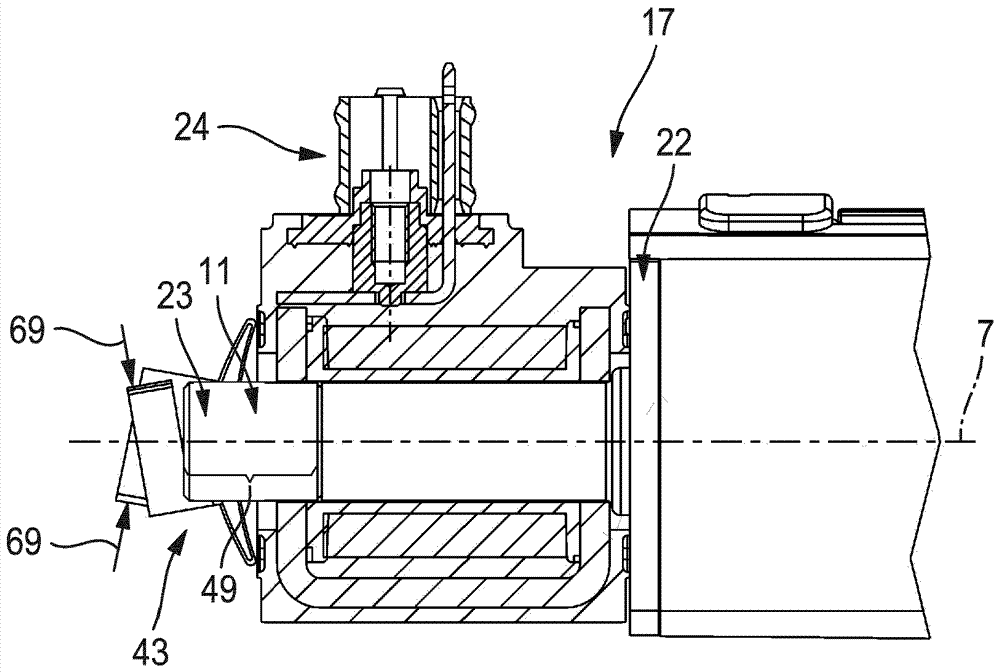
[0046] exist figure 1 In FIG. 1 , a valve designated with reference numeral 1 is shown in its entirety with a base section 2 and a main valve arrangement 3 , a magnetic coil unit 4 and a retaining clip 5 . The base section 2 is preferably detachably mounted on the end side 8 of the main valve device 3 . Starting from a base end face 9 of the base section 2 opposite the end face 8 of the main valve arrangement 3 , the armature tube 6 extends axially along the reference axis 7 . In this case, the magnetic coil unit 4 is pushed axially onto the armature tube 6 so that it bears against the base end face 9 of the base section 2 .

[0047] The armature tube 6 has a free end section 11 opposite the base section 2 , with which the armature tube 6 protrudes beyond the pushed-on magnetic coil unit 4 . The fastening clip 5 is inserted onto this free end section 11 so that the fastening clip 5 is pressed against the magnetic coil unit 4 facing the free end section 11 of the armature tub...


PUM


Abstract

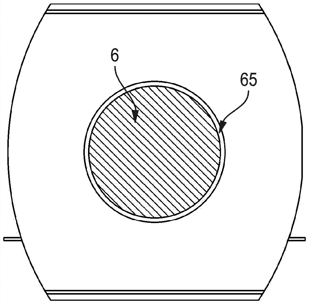
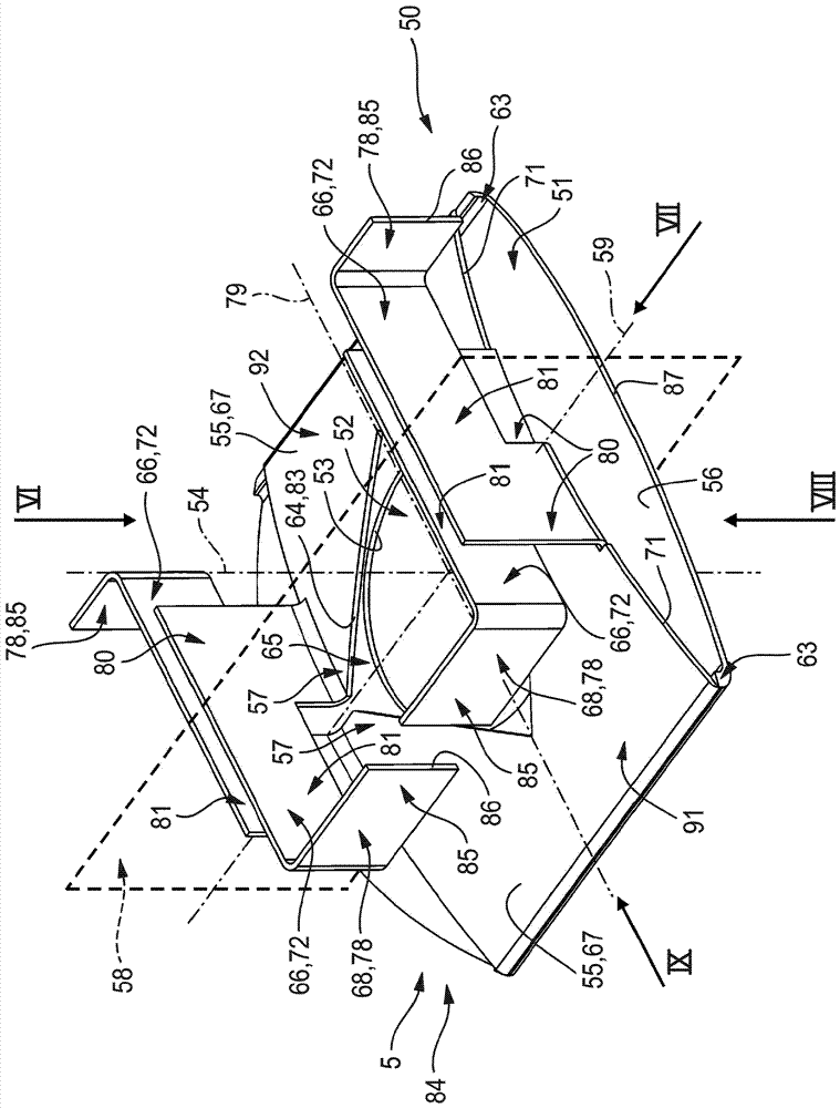
The invention discloses an attachment clip and a valve equipped therewith. Proposed is an attachment clip (5) which can be fitted onto an anchor tube (6) of a valve (1) for attaching a magnet coil unit (4), wherein it comprises a base plate (51) through which passes a centering hole (52). Clamping flanges (55) are folded up on an upper side (56) of the base plate (51) and form a clamping opening (65) which is in line with the centering hole (52), wherein the anchor tube (6) can be clamped in the clamping opening (65). Thus, the attachment clip (5) bears in clamping fashion on the external circumference of the anchor tube (6). On each clamping flange (55) there is arranged at least one actuating tab (66) projecting away from the upper side (67) of the clamping flange (55) and respectively having an actuating surface (68) which can receive an actuating force (69). Within the context of an opening movement (70), the clamping flanges (55) can be elastically spread apart in order to increase the cross section of the clamping opening (65), such that the clamping action on the external circumference of the anchor tube (6) is released, the attachment clip can be removed, and can be installed or removed practically as many times as desired.

Description

technical field [0001] The invention relates to a fastening clip for fastening a magnetic coil unit inserted onto an armature tube of a valve, with: a base plate pierced by a central hole; two folds at mutually opposite folded edge regions of the base plate Clamping wings protruding above the upper side of the base plate, the clamping wings have clamping edges at their free ends facing each other at the end sides, the clamping edges are jointly limited in the axial direction of the vertical axis Clamping opening aligned with the central bore, wherein the clamping wings can be spring-elastically bent relative to the base plate by changing the cross-section of the clamping opening and are utilized in the use position in which the fastening clip is inserted on the armature tube Its clamping edge bears in a pre-tensioned manner in a clamping manner against the outer periphery of the armature tube which passes through the central bore and the clamping opening. [0002] Furthermore...

Claims


Application Information

Patent Timeline
Patent Type & Authority Applications(China)
IPC IPC(8): F16B21/20F16K27/02F16K31/06H01F7/16
CPCF16B21/20F16K27/029F16K31/0675H01F7/1607F16B2/245H01F7/126
Inventor M.鲁塔尔特
Owner FESTO AG & CO KG
Learn More