
An energy-saving excitation current-conducting iron core reactor

A reactor and iron core technology, applied in the direction of magnetic core/yoke, transformer/inductor magnetic core, circuit, etc., to achieve huge benefits, good effects, and low prices

Active Publication Date: 2018-03-23
ZHEJIANG KESHENG ELECTRIC POWER EQUIP
View PDF9 Cites 0 Cited by
  • Summary
  • Abstract
  • Description
  • Claims
  • Application Information

AI Technical Summary

Problems solved by technology

[0004] The purpose of the present invention is to overcome the deficiencies of the prior art, aim at the shortcomings of the existing iron core inductors, and provide an energy-saving excitation current-guiding iron core reactor, which can solve the problems caused by the magnetic flux shunting process. Where the excitation heating occurs and eliminates the vibration and noise caused by the fundamental wave of AC, the design is simple, the benefit is huge, safe, reliable and environmentally friendly

Method used


Image

  • An energy-saving excitation current-conducting iron core reactor
  • An energy-saving excitation current-conducting iron core reactor
  • An energy-saving excitation current-conducting iron core reactor

Examples


Embodiment Construction

[0031] The present invention will be further described below in conjunction with the accompanying drawings, but the present invention is not limited to the following examples.

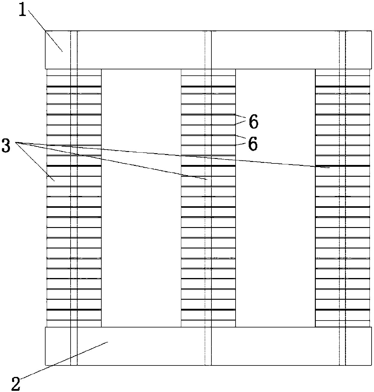
[0032] Such as figure 1 , 2 . As shown in 3, an energy-saving excitation current-conducting iron core reactor includes an iron core, and the iron core includes an upper iron yoke 1, a lower iron yoke 2, a core column 3 and an iron core assembly device, and the core column 3 is located on the upper iron yoke 1 and the lower iron yoke 2, and the coil 4 is hidden outside the core column 3. The core column 3 is formed by stacking a number of magnetic conductive cakes 5, and a gas coil is arranged between every two adjacent magnetic conductive cakes 5. Gap plate 6; the upper and lower ends of the core column 3 are provided with a hollow magnetic cake 7, and the iron core assembly includes a pressing plate 8, a central pull rod 9 and a base 10, the pressing plate 8 is arranged above the upper iron yoke 1, a...


PUM

PropertyMeasurementUnit
thicknessaaaaaaaaaa
thicknessaaaaaaaaaa
thicknessaaaaaaaaaa

Abstract

The invention provides an energy-saving exciting diversion iron-core reactor, which comprises an iron core and an iron core assembly device, wherein the iron core comprises an upper yoke, a lower yoke and core columns; coils are wound outside the core columns in a hidden manner; each core column is formed by stacking multiple groups of air gap plates and magnetic conductive discuses at intervals and is arranged between the upper yoke and the lower yoke; hollow magnetic guide cakes are arranged between each core column and the upper yoke and between each core column and the lower yoke respectively; the iron core assembly device comprises bases, center pull rods arranged on the base and pressure plates; the pressure plates are arranged at the upper part of the upper yoke; the bases are arranged at the lower part of the lower yoke; each center pull rod runs through predefined holes in the upper yoke, the lower yoke and the corresponding core column; the upper end of each center pull rod is fixed to the corresponding pressure plate; and the lower end of each center pull rod is fixed to the corresponding base. The energy-saving exciting diversion iron-core reactor has the beneficial effects that (1) the exciting heating problem in the magnetic flux shunting process is solved; (2) vibration noise caused by an AC fundamental wave is eliminated; and (3) the total loss is reduced by 25% under the same conditions of a traditional product and the hot-spot temperature rise is reduced to within 90K from more than 150K.

Description

technical field [0001] The invention relates to an iron-core reactor, in particular to an energy-saving excitation current-guiding iron-core reactor, which belongs to the field of electric equipment. Background technique [0002] At present, all or most of the magnetic flux of the iron core reactor is closed through the iron yoke magnetic circuit of the core column. When the iron core reactor works in the saturated state of the iron core, its inductance value is greatly reduced. The reactor made by using this characteristic is called Saturated Reactor. The iron core reactor will generate heat when it is working, and the heating point is at the center of the iron yoke, and the heat dissipation condition is poor. After a long time of operation, the temperature of the heating point will cause the overall iron yoke to overheat through the heat conduction of the silicon steel sheet, and the serious one can be as high as More than 200 degrees Celsius. The reason is that when a l...

Claims


Application Information

Patent Timeline
Patent Type & Authority Patents(China)
IPC IPC(8): H01F27/24H01F3/14
CPCH01F3/14H01F27/24
Inventor 姜斌姜诚渊崔汉国
Owner ZHEJIANG KESHENG ELECTRIC POWER EQUIP
Learn More