Key assembly and electronic device having the same

a technology of electronic devices and key assemblies, applied in the direction of emergency actuators, contact surface shapes/structures, switch side locations, etc., can solve the problems of fpcb itself being relatively expensive, side key assemblies adopting this tact switch can have other problems, and the fpcb type does not provide excellent user experience. , to achieve the effect of enhancing elasticity

Active Publication Date: 2016-02-09
SAMSUNG ELECTRONICS CO LTD
View PDF17 Cites 0 Cited by
  • Summary
  • Abstract
  • Description
  • Claims
  • Application Information

AI Technical Summary

Benefits of technology

[0010]An exemplary aspect of the present invention is to solve at least some of the above-mentioned problems and / or disadvantages and to provide at least the advantages described below. Accordingly, an exemplary aspect of the present invention is to provide a key assembly for removing a vibration noise and improving click feeling and tactile response and an electronic device having the same.
[0011]Another exemplary aspect of the present invention is to provide a key assembly for simultaneously improving click feeling and tactile response of an electronic device, reducing its costs, and enhancing its space utilization and an electronic device having the same.
[0014]In accordance with another exemplary aspect of the present invention, an electronic device includes: a key assembly disposed such that a part thereof is extending into and exposed within the interior of the electronic device; and a tact switch disposed in the electronic device in alignment with the key assembly to perform an electric switching operation in response to a force exerted on the key assembly, wherein the key assembly includes a key case installed to be exposed to the outside of the electronic device, a key body of elastic materials which is combined and fixed with the key case, wherein the key case is attached to an outer surface of the key body and adapted to receive and support the key body, the key case being comprised of contact projections, each of the contact projections, having an inner hollow cavity, wherein each of the contact projections is protruded and formed in a direction from the key body and extending toward the tact switch, a push projection which is formed within the hollow cavity and is formed to be protruded on a surface of the key body in a direction toward the switch device wherein the hollow cavity provides a predetermined gap between the push projection and an inner wall of the contact projections; and one or more concave groove portions formed surrounding each of the contact projections of the key body to provide enhanced elasticity of each of the contact projections and wherein the key body is installed such that a contact surface of each of the contact projections is in contact with and pushed back by a certain distance by a force exerted by a contact head of the tact switch.

Problems solved by technology

A switch of the FPCB type does not provide the user with excellent performance with respect to click feeling or tactile response.
Also, because an FPCB itself is relatively expensive, it is common for standard or ordinary devices to adopt the tact switch type.
However, while in case of a tact switch, has the benefit of being relatively inexpensive, a side key assembly adopting this tact switch can have other problems.
The use of a tact switch can cause a result in which there are problems such as a vibration noise and deterioration in click feeling due to the accumulation of various tolerances such as a tolerance of a Surface Mounted Device (SMD) of the PBA and an injection molding tolerance of a side key formed by an injection molding type.
This results in the increase of research and development costs and nonetheless does not provide an ideal solution for an effect for improving the vibration noise and click feeling.
In addition, when installing additional portions and components to improve click feeling, space utilization of the side key assembly may deteriorate.

Method used


Image

  • Key assembly and electronic device having the same
  • Key assembly and electronic device having the same
  • Key assembly and electronic device having the same

Examples


Embodiment Construction

[0020]Exemplary embodiments of the present invention will now be described herein below with reference to the accompanying drawings. In the following description, well-known functions or constructions may not be described in detail when they would obscure appreciation of the present invention by a person of ordinary skill in the art with unnecessary detail of the well-known functions and structures. Also, the terms used herein are defined according to the functions of the present invention as would be understood by a person of ordinary skill in the art. Thus, the terms may vary depending on user's or operator's intension and usage. That is, the terms used herein must be understood based on the descriptions made herein in view of the ordinary level of skill in the art.

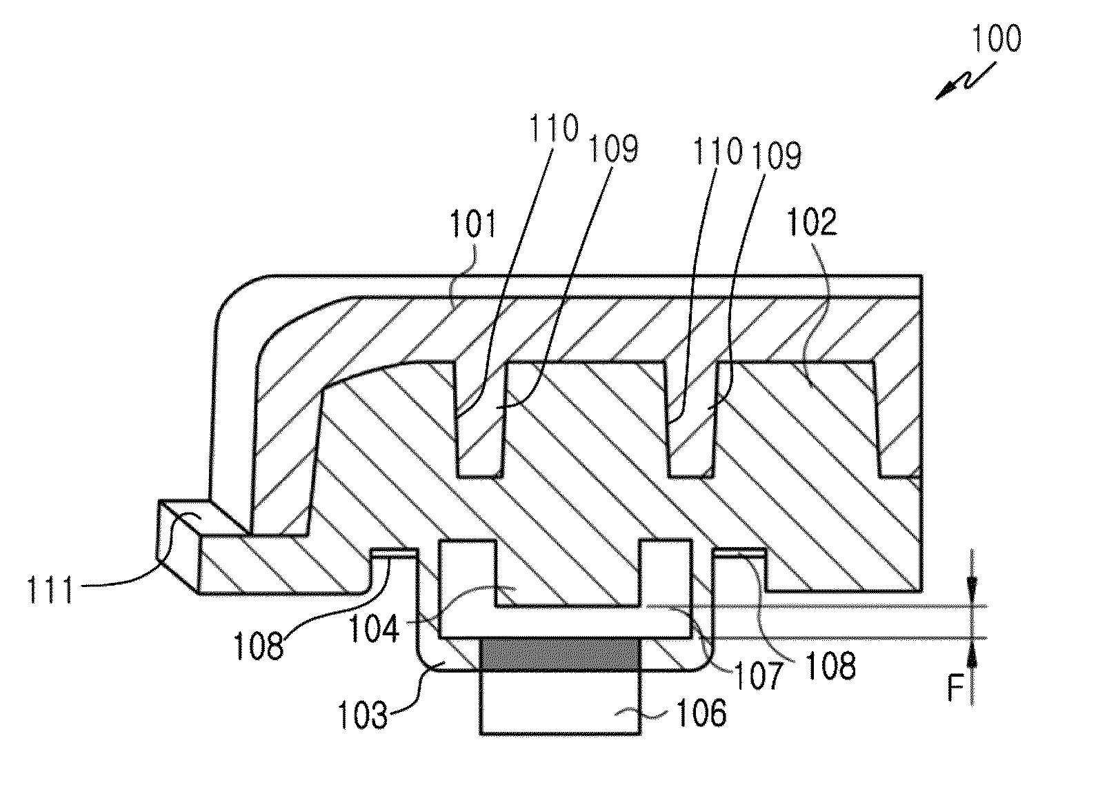
[0021]In describing various embodiments of the present invention, an electronic device may be at least one of various electronic devices, each of them which has a key assembly capable of performing a physical key button...


PUM


Abstract

A key assembly which is configured to provide improved click feeling to a user and an electronic device having the same are provided. The key assembly includes a key body of elastic materials and contact projections, each of the contact projections which is protruded and formed from the key body and presses a switch device spaced apart from the key body by a gap providing a certain interval, wherein the key body is installed such that a contact surface of each of the contact projections is in contact with and pushed back by a certain distance by a pre-loading force of the switch device.

Description

CLAIM OF PRIORITY[0001]This application claims the benefit under 35 U.S.C. §119(a) from a patent applications filed in the Chinese Patent Office on Jun. 26, 2012 and assigned Serial No. 201220303763.X and filed in the Korean Intellectual Property Office on May 28, 2013 and assigned Serial No. 10-2013-0060224, the entire disclosure of which is hereby incorporated by reference in its entirety.BACKGROUND[0002]1. Field of the Invention[0003]The present disclosure relates to a key assembly. More particularly, the present invention relates to a key assembly which is configured to provide improved click feeling and tactile sensation to a user and an electronic device having the same.[0004]2. Description of the Related Art[0005]In general, each of electronic devices such as a mobile phone, a Moving Picture Experts Group (MPEG) audio layer 3 (MP3) player, a tablet Personal Computer (PC) has a key assembly to enable quick and precise control a user wants.[0006]For example, a side key in the k...

Claims


Application Information

Patent Timeline
Patent Type & Authority Patents(United States)
IPC IPC(8): H01H13/14H01H13/12H01H13/85H01H1/12
CPCH01H1/12H01H13/85H01H2221/044H01H2221/062H01H2221/074H01H2225/028H01H2235/016
Inventor PARK, JEONG-SEOKPARK, JOON-SEOSEO, KWANG-SUJEON, YONG-WOO
Owner SAMSUNG ELECTRONICS CO LTD
Why Eureka
Try Eureka