
Capillary viscometer capable of realizing automatic quantification and testing method thereof

A technology of capillary viscometer and capillary tube, which is applied in the direction of direct current flow characteristic measurement, etc., which can solve the problems of difficult cleaning, poor measurement timeliness, and low degree of automation

Active Publication Date: 2016-09-07
湖南慑力电子科技有限公司
View PDF4 Cites 2 Cited by
  • Summary
  • Abstract
  • Description
  • Claims
  • Application Information

AI Technical Summary

Problems solved by technology

[0009] The purpose of the present invention is to provide a gravity-type glass capillary viscometer for automatic viscometers that can solve the problems of traditional viscosity measuring instruments such as sample color limitation, poor measurement timeliness, difficult cleaning, low degree of automation, and waste of resources. It realizes the function of automatic quantification, the measurement speed is fast, the cleaning is convenient and the cleaning solution is saved, and it is not limited by the color of the sample at all

Method used


Image

  • Capillary viscometer capable of realizing automatic quantification and testing method thereof
  • Capillary viscometer capable of realizing automatic quantification and testing method thereof
  • Capillary viscometer capable of realizing automatic quantification and testing method thereof

Examples


Embodiment 1

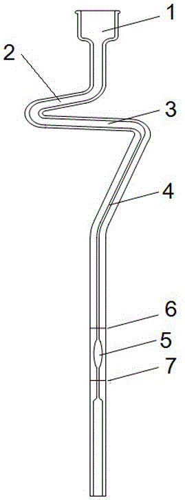
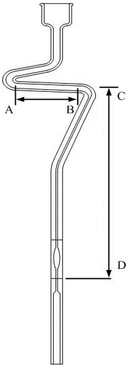
[0067] This embodiment provides a capillary viscometer capable of automatic quantification, including a kinematic viscometer with a folded tube, and the kinematic viscometer with a folded tube includes a sampling cup 1, a draft tube 2, a cross arm 3, and a capillary 4 connected in sequence , the measuring bulb 5, and the upper scale line 6 and the lower scale line 7 respectively positioned above and below the measuring bulb 5, the capillary viscometer also includes a branch pipe 8, and one end of the branch pipe 8 is communicated with the cross arm 2, and it communicates Located on the side near the draft tube 2, the other end of the branch pipe 8 communicates with the closed pipe 9, the inner diameter of the branch pipe 8 is 2mm, the inner diameter of the closed pipe 9 is 4mm, the inner diameter of the capillary 4 is 0.5mm, and the inner diameter of the cross arm 3 is 4mm, The length of branch pipe 8 is 15mm, and valve is established on closed pipe 9.


PUM

PropertyMeasurementUnit
lengthaaaaaaaaaa
lengthaaaaaaaaaa

Abstract

The invention relates to a capillary viscometer capable of realizing automatic quantification and a testing method thereof. The capillary viscometer comprises a tube-bending type kinematic viscometer; the tube-bending type kinematic viscometer comprises a sample introduction cup, a honeycomb duct, a transverse arm, a capillary tube and a measuring bulb sphere which are successively communicated, and an upper scale mark and a lower scale mark respectively located above and below the measuring bulb sphere; the capillary viscometer further comprises a branch pipe; and one end of the branch pipe is communicated with the transverse arm, and the internal diameter of the branch pipe is smaller than the internal diameter of the transverse arm and greater than internal diameter of the capillary tube. According to the invention, since the branch pipe is arranged on the transverse arm of the viscometer, a sample located between the sample introduction cup and the branch pipe has enough time to thoroughly flow out from the branch pipe before a sample in the capillary tube reaches the upper scale mark, so it is guaranteed that the tail end of the sample is located at the edge of the joint of the branch pipe and the transverse arm, the viscometer is calibrated and the height of a liquid column in testing of a sample each time is identical to the length of the capillary tube; and thus, accuracy and repeatability of viscosity testing are improved.

Description

technical field [0001] The invention relates to a capillary viscometer capable of automatic quantification and a testing method thereof, belonging to the field of Newtonian liquid viscosity analysis. Background technique [0002] There are many measurement methods for the kinematic viscosity of fluid Newtonian liquids. The current domestic measurement methods include capillary measurement, rotation measurement, falling ball method, vibration method, plate method, and viscosity cup method. Among them, the gravity glass capillary measurement method in the capillary measurement tube method is the method with the highest accuracy among the existing measurement methods, and it is also the most commonly used method. [0003] The method of measuring the kinematic viscosity of a Newtonian liquid with a glass capillary is to measure the time for a certain volume of liquid to flow through a calibrated glass capillary viscometer under gravity at a constant temperature, the product of t...

Claims


Application Information

Patent Timeline
Patent Type & Authority Applications(China)
IPC IPC(8): G01N11/06
CPCG01N11/06
Inventor 石强朱自强
Owner 湖南慑力电子科技有限公司
Learn More