
Square stiff column prefabricated section adjustable formwork system and its construction method

A construction method and assembly technology, which is applied in the field preparation of formwork/formwork/work frame, building components, construction, etc., and can solve the work of the formwork system that cannot adapt to the diameter reduction, reinforcement and removal of the concrete square stiff column section Problems such as large quantity and inability to turn over the pull screw to achieve good physical quality, significant economic and social benefits, and flexible and convenient disassembly

Active Publication Date: 2018-08-07
CHINA CONSTR FIFTH ENG DIV CORP LTD
View PDF10 Cites 0 Cited by
  • Summary
  • Abstract
  • Description
  • Claims
  • Application Information

AI Technical Summary

Problems solved by technology

[0003] The disadvantage of this type of concrete square stiff column formwork reinforcement system is that the operation is relatively cumbersome, and the workload of assembling, strengthening and dismantling the formwork system is relatively large, requiring a lot of labor and taking a long time; The pulling screw cannot be used in turnaround, and a lot of materials are wasted; the steel keel is too heavy, and it is extremely inconvenient to carry it manually; the number of structural parts is large, and the material loss is large; the steel formwork has poor applicability and cannot adapt to the diameter reduction of the concrete square rigid column section

Method used


Image

  • Square stiff column prefabricated section adjustable formwork system and its construction method
  • Square stiff column prefabricated section adjustable formwork system and its construction method
  • Square stiff column prefabricated section adjustable formwork system and its construction method

Examples


Embodiment Construction

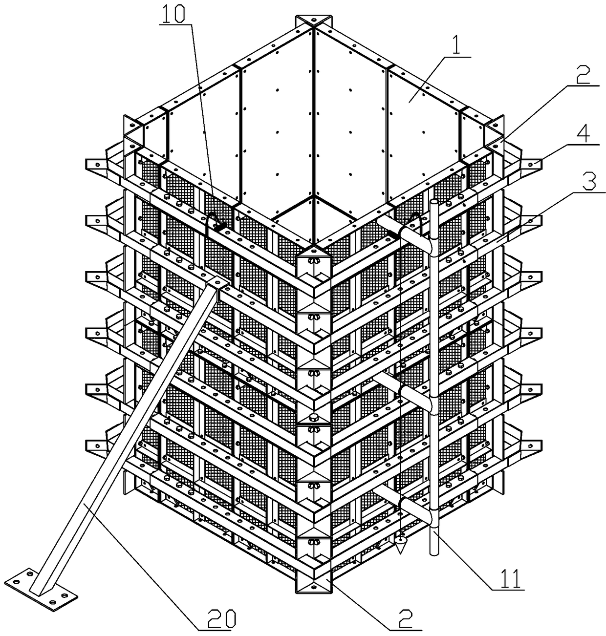
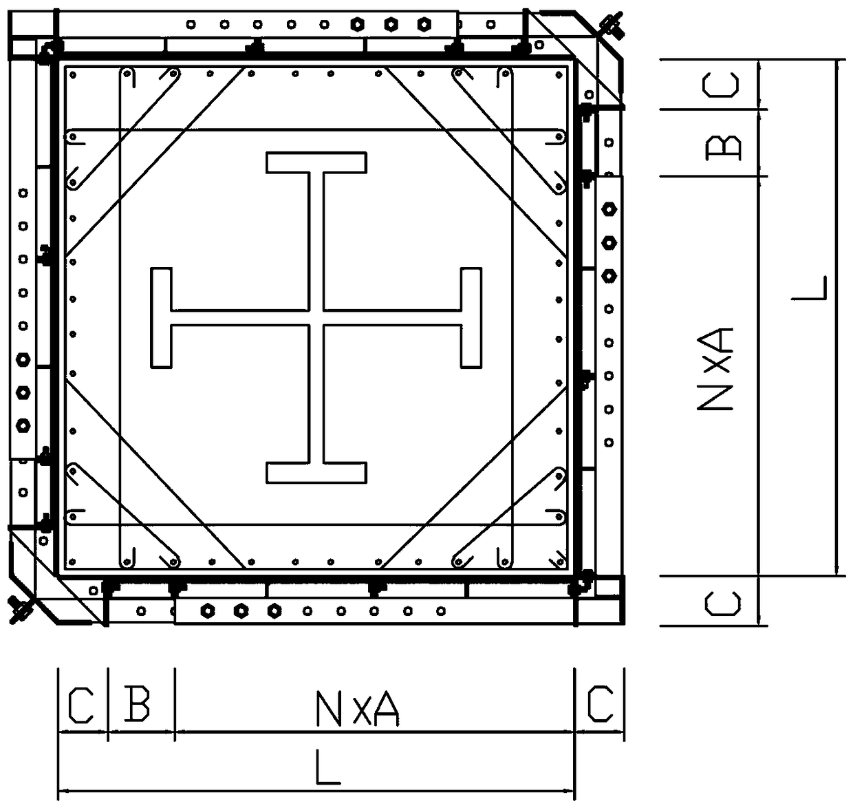
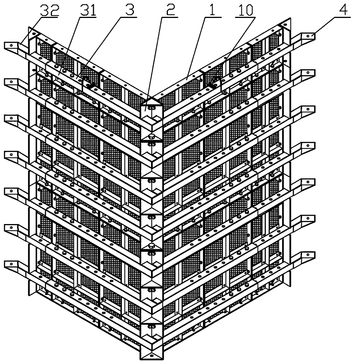
[0023] like Figure 1 to Figure 3 As shown in the figure, a square rigid column assembled cross-section adjustable formwork system is a rectangular structure composed of four surface formworks 1, and every two surface formworks 1 are connected by angle steel positioning pieces 2, and the vertical angle steel positioning pieces 2 There are several evenly distributed rectangular grooves in the direction, and several limit beams 3 are arranged on the outer surface of the surface formwork 1, and the two ends of the limit beams 3 are respectively seated in the rectangular grooves, corresponding to the The limit beam 3 is vertically connected; the surface formwork 1 is composed of several standard unit formworks and a non-standard unit formwork connected to each other. The standard formwork and the non-standard formwork are composed of angle steel, corner codes and formwork, and the periphery is sealed with a frame with holes. It is convenient to connect the two unit formworks; the ...


PUM


Abstract

The invention relates to a fabricated section-adjustable formwork system for square stiff pillars. The fabricated section-adjustable formwork system is of a rectangular structure formed by four surface formworks. Every two surface formworks are connected with each other through angle-steel positioning members. A plurality of evenly distributed rectangular grooves are formed in each angle-steel positioning member vertically. A plurality of limiting cross beams are arranged on the outer surfaces of the surface formworks. Two ends of each limiting cross beam are located in the corresponding rectangular grooves, and are vertically connected with the corresponding limiting cross beams on the adjacent surface formwork. Each surface formwork is formed by connection of a plurality of standard unit formworks and a non-standard unit formwork. Each limiting cross beam is formed by inserted connection of outer square steel and inner square steel, and the length of each limiting cross beam is adjusted according to the width of the corresponding surface formwork. The formwork system has the advantages that during turnover, damage degree is low, construction speed is high, auxiliary measures are few, and requirements on operation levels of operators are low; the formwork system is applicable to construction requirements of section changes of the square stiff pillars, is environment friendly and has high economic and social benefits.

Description

technical field [0001] The invention relates to a formwork system with adjustable cross-section of a square rigid column assembly and a construction method thereof, belonging to the construction field. Background technique [0002] As we all know, the current formwork reinforcement system for concrete square rigid columns mainly uses panels (wood, plywood, plastic boards, etc.) + profiled steel or wooden frame secondary corrugated + profiled steel main corrugated + connectors (pull bolts, gable clips, nuts, etc.) , Steel formwork + steel keel + connectors, steel-wood composite formwork + steel keel + connectors and other reinforcement methods, usually such methods are assembled into a formwork reinforcement system for concrete square rigid columns through manual loose assembly. [0003] The disadvantage of this type of concrete square stiff column formwork reinforcement system is that the operation is relatively cumbersome, and the workload of assembling, strengthening and d...

Claims


Application Information

Patent Timeline
Patent Type & Authority Patents(China)
IPC IPC(8): E04G13/02
CPCE04G13/025E04G13/026
Inventor 刘文伍黎杨生王瑞
Owner CHINA CONSTR FIFTH ENG DIV CORP LTD
Learn More