Seat armrest height adjustment mechanism and seat
A height adjustment mechanism and armrest technology, applied in the direction of armrests, seats, chairs, etc., can solve the problem of inability to adjust the height, and achieve the effect of simple structure, consistency assurance, and convenient use
- Summary
- Abstract
- Description
- Claims
- Application Information
AI Technical Summary
Problems solved by technology
Method used
Image

Examples
Embodiment 1
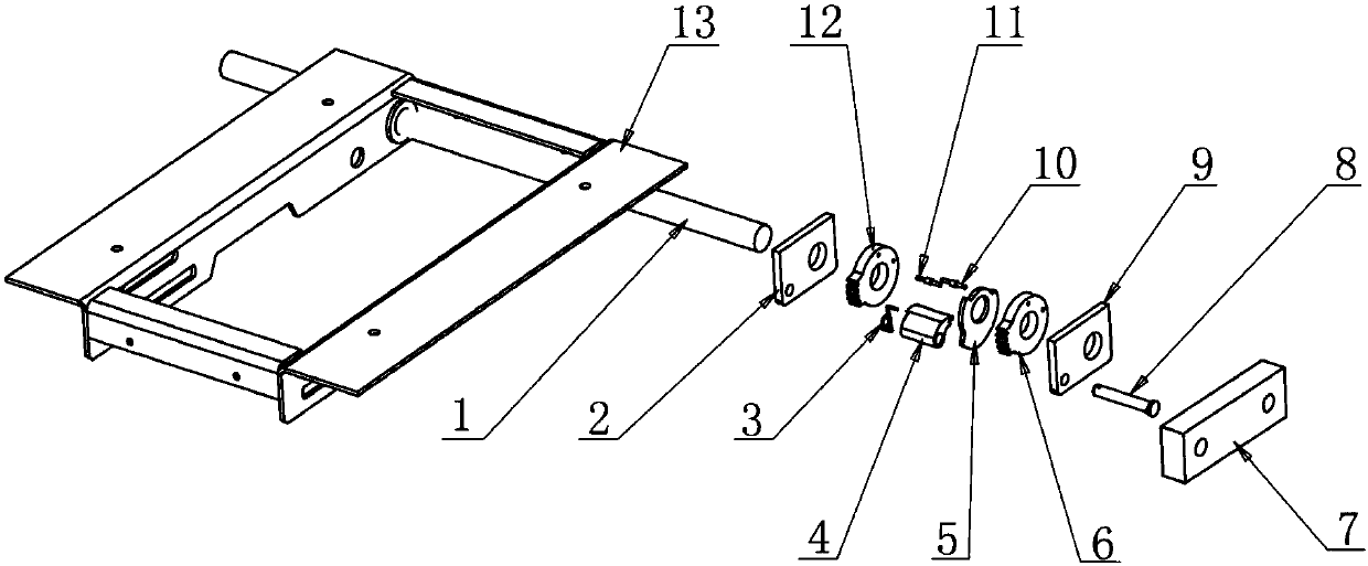
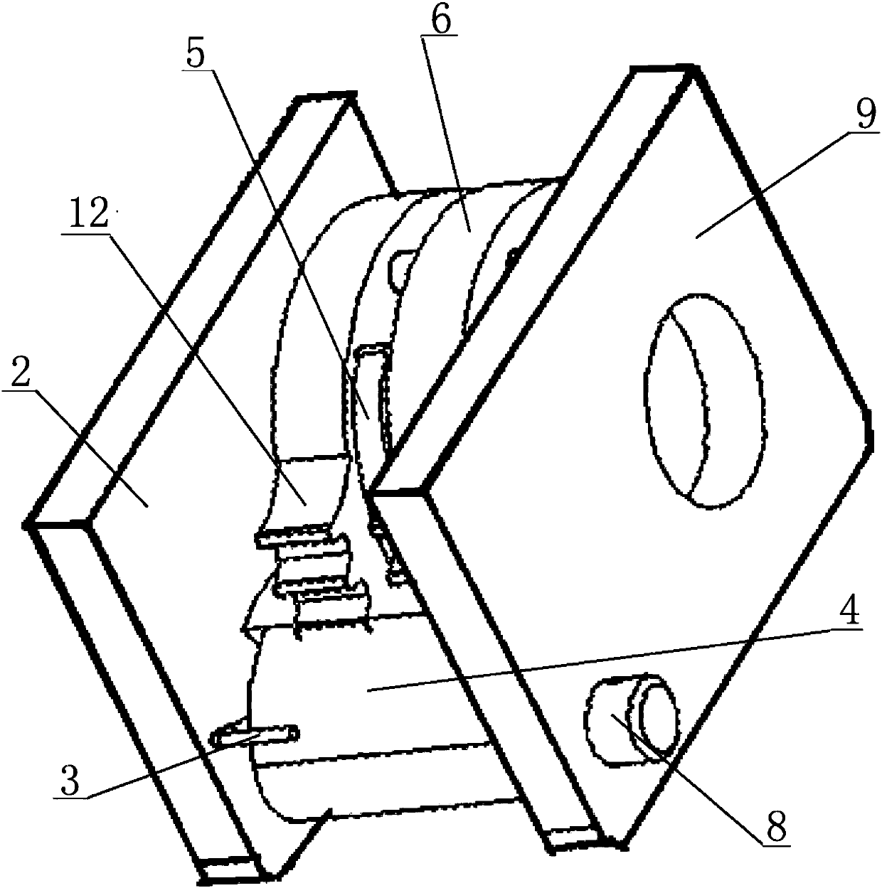
[0033] Such as Figure 1-14 , a seat armrest height adjustment mechanism, including a rotating shaft 1 and a rotation adjustment member, the rotation adjustment member includes a first mounting plate 2, a second mounting plate 9, a first ratchet 12, a second ratchet 6, a cam 5, a first The limit pin 11, the second limit pin 10, the ratchet 4, the spring 3 and the pin stop connecting shaft 8.
[0034] The first mounting plate 2 , the first ratchet 12 , the cam 5 , the second ratchet 6 and the second mounting plate 9 are sequentially fixed on the rotating shaft 1 , and the cam 5 can rotate flexibly. The first limit pin 11 and the second limit pin 10 are fixed on the first ratchet 12 and the second ratchet 6 at the same time, and play the role of the limit cam 5 . The ratchet 4 is fixed on the first mounting plate 2 and the second mounting plate 9 with the spring 3 and the pin stop connecting shaft 8 to ensure that the ratchet 4 is connected to the first ratchet 12 and the secon...
Embodiment 2
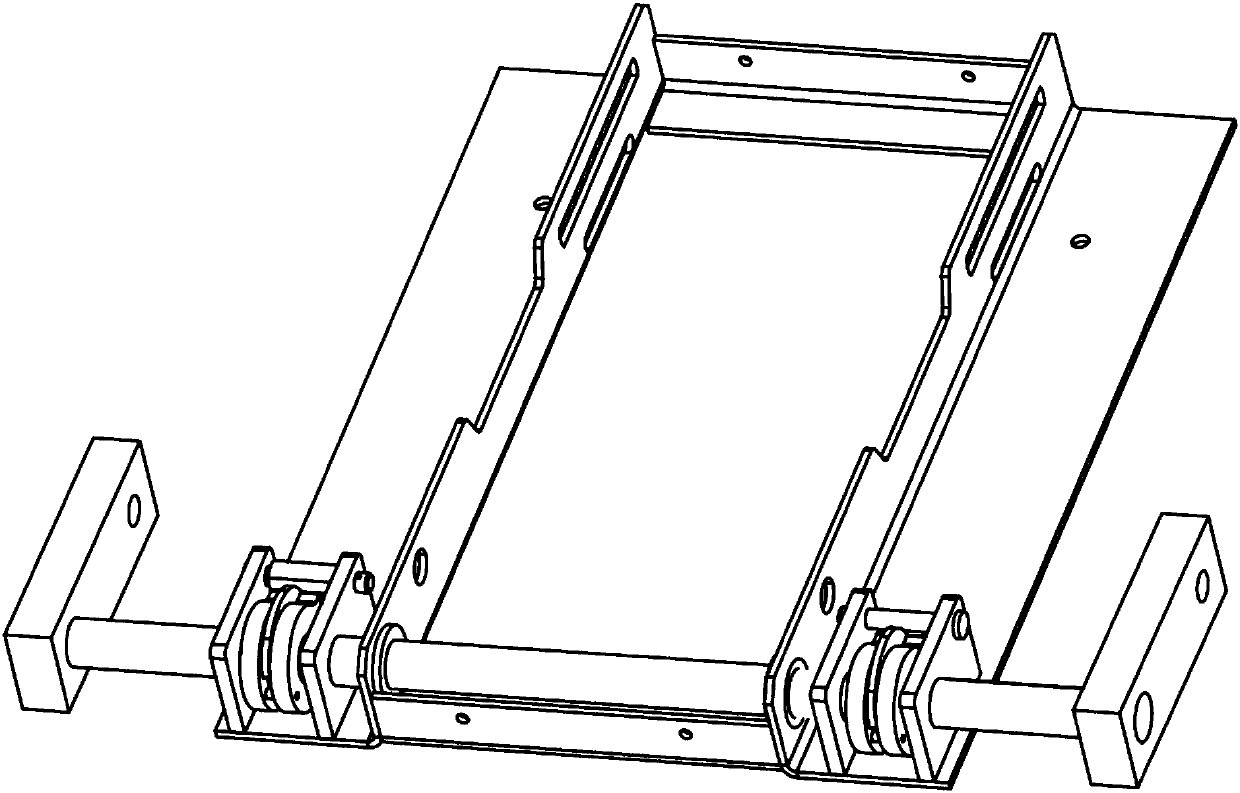
[0042] The rotating shaft 1 is installed on the seat support frame 13 and stretches out, and the rotation is flexible and reliable. The two ends of the rotating shaft 1 are connected with the armrest mounting bracket 7, and there are two rotating adjustment members, which are symmetrically installed on the rotating shaft 1, between the seat support frame 13 and the armrest mounting bracket 7. Armrest 14 is assembled with armrest mounting bracket 7 .
[0043] When it is necessary to adjust the height of the armrest, you only need to buckle the armrest buckle groove 15 in the armrest 14 with your hands backwards, and drive the rotating shaft 1, the first ratchet 12 and the second ratchet 6 to rotate backwards at the same time. Under the force of the spring, the first ratchet 12 and each tooth of the second ratchet 6 are naturally locked in sequence, and the cam 5 will also rotate at the same time. Rotate backward again, to prevent that the angle of the armrest is adjusted too l...
Embodiment 3
[0045] A seat armrest height adjustment mechanism is the same as Embodiment 1 except for the following differences.
[0046] The first mounting plate 2 is respectively provided with a first through hole 21 of the first mounting plate, a second through hole 22 of the first mounting plate and a third through hole 22 of the first mounting plate. The third through holes 22 of the first mounting plate are installed on the four corners of the first mounting plate 2 . The second mounting plate 9 is provided with a second mounting plate through hole 91 , a second mounting plate second through hole 92 and a second mounting plate third through hole 92 . The third through holes 92 of the second mounting plate are installed on the four corners of the second mounting plate 9 .
[0047]The seat armrest height adjustment mechanism also includes an adjuster shell 16 and a snap ring pin 15, and the adjuster shell 16 is connected with the second mounting plate 9 with bolts for decoration and p...
PUM
 Abstract
Description
Claims
Application Information
 - Generate Ideas
- Intellectual Property
- Life Sciences
- Materials
- Tech Scout
- Unparalleled Data Quality
- Higher Quality Content
- 60% Fewer Hallucinations
Browse by: Latest US Patents, China's latest patents, Technical Efficacy Thesaurus, Application Domain, Technology Topic, Popular Technical Reports.
© 2025 PatSnap. All rights reserved.Legal|Privacy policy|Modern Slavery Act Transparency Statement|Sitemap|About US| Contact US: help@patsnap.com