Special dipping equipment for PVC negative ion antibacterial gloves and dipping process thereof
A negative ion antibacterial and impregnating equipment technology, which is applied in applications, household components, household appliances, etc., can solve the problems of not being able to protect the health of users and patients, and not endowing PVC gloves with anti-bacteria and sterilization, so as to shorten the impregnation time and improve the impregnation speed effect
- Summary
- Abstract
- Description
- Claims
- Application Information
AI Technical Summary
Problems solved by technology
Method used
Image
Examples
Embodiment 1
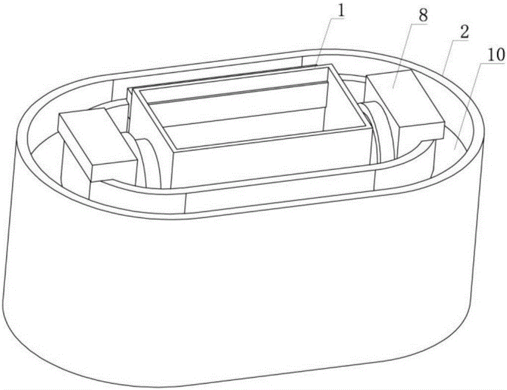
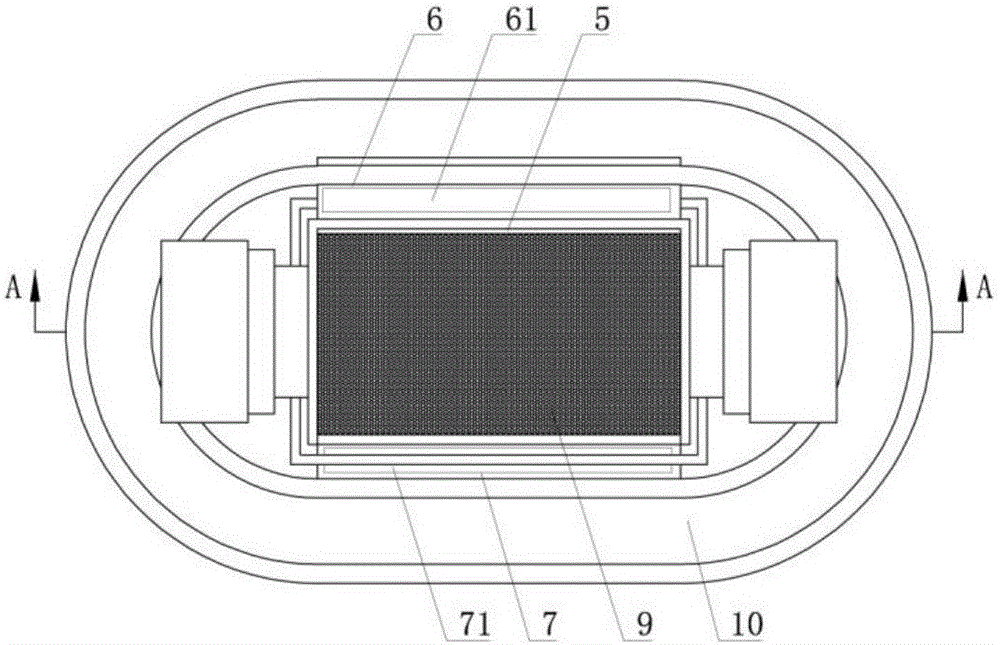
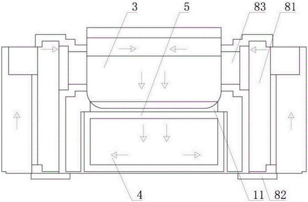
[0043] Such as figure 1 , figure 2 , image 3 , Figure 4 As shown, the special dipping equipment for PVC negative ion antibacterial gloves includes a slurry tank 1, a diversion tank 2 located on the outer ring of the slurry tank 1, a slurry tank 1 includes a dipping tank 3, a sedimentation tank 4 located below the dipping tank 3, and isolated Plate 5, feed channel 6, discharge channel 7, support frames 8 for supporting the slurry tank 1 are provided on both sides of the slurry tank 1, the isolation plate 5 is located between the dipping tank 3 and the sedimentation tank 4, and the isolation plate 5 Inlaid with a filter bag 9; the diversion groove 2 is annular, and the diversion groove 2 is provided with a conveyor belt 10, which is used to drive the driving motor (not shown in the figure) for driving the conveyor belt 10. The height of the rear end of the conveyor belt 10 is greater than that of the front end The driving motor controls the circular action of the conveyor ...
Embodiment 2
[0050] Such as figure 1 , figure 2 , image 3 , Figure 4 As shown, the special dipping equipment for PVC negative ion antibacterial gloves includes a slurry tank 1, a diversion tank 2 located on the outer ring of the slurry tank 1, a slurry tank 1 includes a dipping tank 3, a sedimentation tank 4 located below the dipping tank 3, and isolated Plate 5, feed channel 6, discharge channel 7, support frames 8 for supporting the slurry tank 1 are provided on both sides of the slurry tank 1, the isolation plate 5 is located between the dipping tank 3 and the sedimentation tank 4, and the isolation plate 5 Inlaid with a filter bag 9; the diversion groove 2 is annular, and the diversion groove 2 is provided with a conveyor belt 10, which is used to drive the driving motor (not shown in the figure) for driving the conveyor belt 10. The height of the rear end of the conveyor belt 10 is greater than that of the front end The driving motor controls the circular action of the conveyor ...
PUM
 Abstract
Description
Claims
Application Information
 - Generate Ideas
- Intellectual Property
- Life Sciences
- Materials
- Tech Scout
- Unparalleled Data Quality
- Higher Quality Content
- 60% Fewer Hallucinations
Browse by: Latest US Patents, China's latest patents, Technical Efficacy Thesaurus, Application Domain, Technology Topic, Popular Technical Reports.
© 2025 PatSnap. All rights reserved.Legal|Privacy policy|Modern Slavery Act Transparency Statement|Sitemap|About US| Contact US: help@patsnap.com


