
Automatic spot welding method for battery electrodes

An automatic spot welding and battery electrode technology, applied in resistance welding equipment, welding equipment, welding equipment, etc., can solve the problems of no significant increase in efficiency, deviation of displacement, and high requirements for welding employees with manual participation, and achieve manual participation. Simple and easy to implement, avoid wrong welding or welding damage, low manual participation

Inactive Publication Date: 2016-09-07
安徽安耐捷新能源科技有限公司
View PDF5 Cites 11 Cited by
  • Summary
  • Abstract
  • Description
  • Claims
  • Application Information

AI Technical Summary

Problems solved by technology

[0003] Manual welding machines are inefficient, have high requirements for welding staff, and poor product consistency. However, automatic welding machines have two obvious defects, whether it is welding needle movement or battery movement. First, the deviation of displacement is inevitable, while welding The surface is very small, and it is prone to problems such as wrong welding or welding damage. Second, when welding, the batteries are still welded one by one. The time interval between each welding is the moving time of the welding needle or battery and the removal of the welding needle point. The moving time, although the degree of manual participation has been greatly reduced, but the efficiency has not been significantly improved

Method used


Image

  • Automatic spot welding method for battery electrodes
  • Automatic spot welding method for battery electrodes
  • Automatic spot welding method for battery electrodes

Examples


Embodiment Construction

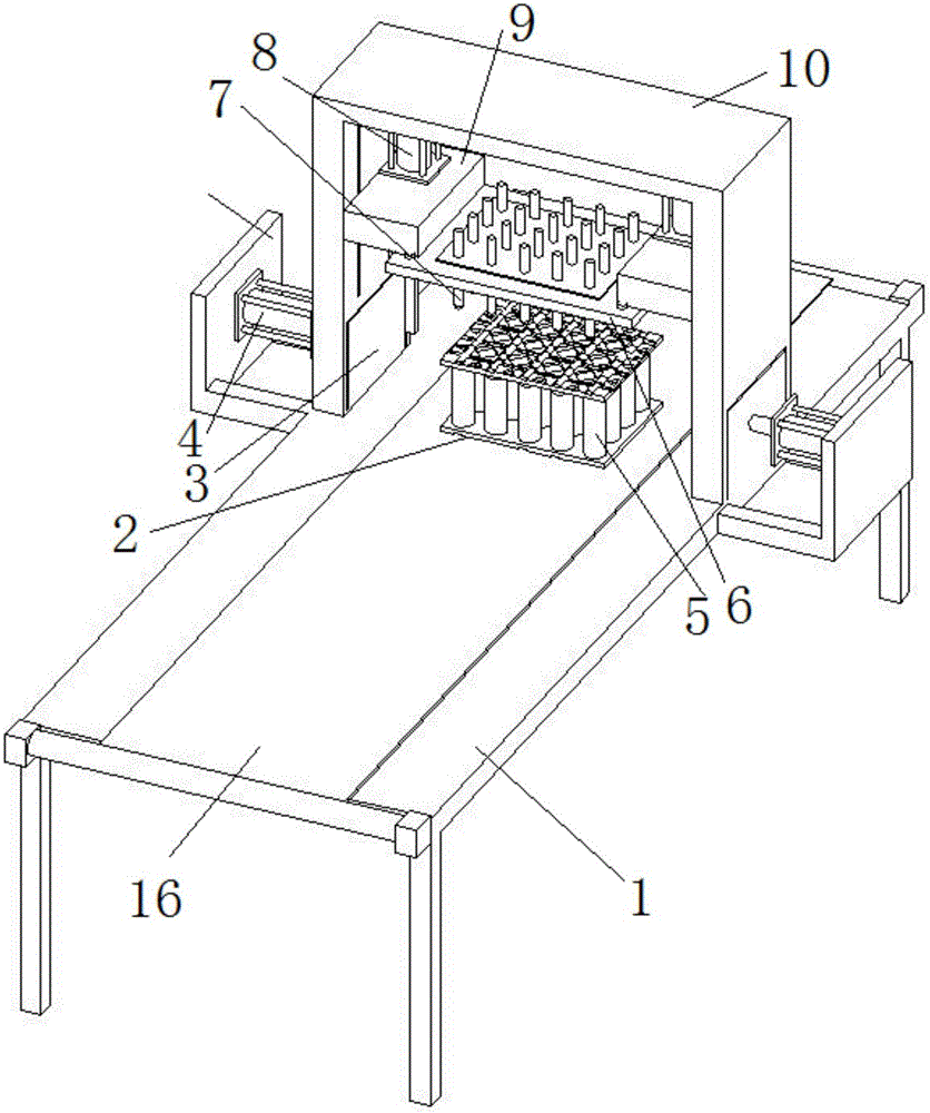
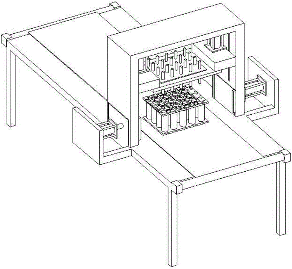
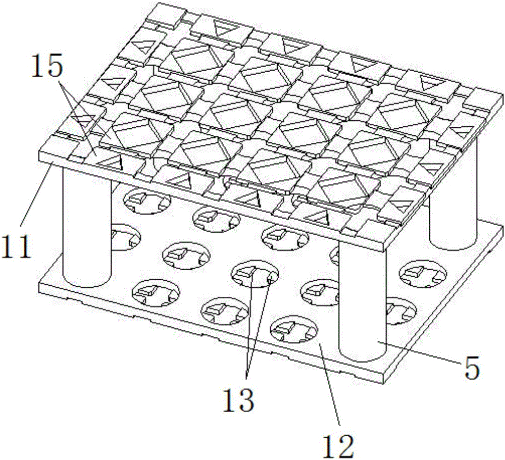
[0019] Such as Figure 1 ~ Figure 3 An automatic spot welding method for battery electrodes is shown. The automatic spot welding machine includes a workbench 1, a battery fixing mechanism 2, a spot welding mechanism, and a positioning and clamping mechanism. The positioning and clamping mechanism includes two oppositely arranged retractable clamping blocks 3. The two clamping blocks 3 are stretched and retracted respectively by the two clamping cylinders 4, and the battery fixing mechanism 2 is arranged between the two clamping blocks 3;

[0020] The battery fixing mechanism 2 is fixed with a plurality of vertical batteries 5, and the electrodes of the batteries to be welded are set upward; 5 are in one-to-one correspondence, and each group of welding pins 7 is arranged above the corresponding battery 5, and the lower pressing plate 6 is driven down by the lower pressing telescopic mechanism. In the pressed down state of the lower pressing plate 6 , the welding pin 7 is in co...


PUM


Abstract

The invention discloses an automatic spot welding method for battery electrodes. The automatic spot welding method of the battery electrodes comprises the steps that (a) a plurality of batteries are vertically fixed to battery fixing mechanisms, the to-be-welded electrode of the batteries are arranged upwards and exposed out from clamping holes of upper clamping blocks, and the multiple battery fixing mechanisms are sequentially placed on a conveying belt; (b) a system controls the conveying belt to drive the first battery fixing mechanism to a station below a pressing plate, and the two clamping blocks are driven by clamping air cylinders on the two sides to be ejected and clamp the two ends of the first battery fixing mechanism correspondingly; and (c) piston rods of two pressing air cylinders are ejected to drive the pressing plate to press, a plurality of sets of welding needles make contact with the to-be-welded electrodes of the batteries in a one-to-one corresponding mode, and the system conducts discharging welding on the to-be-welded electrodes of the battery below all the sets of welding needles in sequence. The automatic spot welding method for the battery electrodes has the following advantages that spot welding is conducted on the to-be-welded electrodes of the multiple batteries at the same time, welding is accurate, mistaken welding or welding damage is avoided, and the welding efficiency is greatly improved.

Description

technical field [0001] The invention relates to the technical field of batteries, in particular to an automatic spot welding method for battery electrodes. Background technique [0002] The traditional manual spot welding machine is to move the battery to be welded on the fixed welding chassis, and the fixed welding pin on the top is pressed down to the battery to discharge welding. There are two types of automatic spot welding machines. One is that the battery pack is fixed on the welding table. , the upper welding needle device has a moving track from front to back, left and right, and the moving position is controlled by a microcomputer and pressed down for welding. The impact time of the needle and the displacement of the manipulator are matched for welding. [0003] Manual welding machines are inefficient, have high requirements for welding staff, and poor product consistency. However, automatic welding machines have two obvious defects, whether it is welding needle mo...

Claims


Application Information

Patent Timeline
IPC IPC(8): B23K11/11B23K37/04B23K101/36
CPCB23K11/11B23K37/0435B23K2101/36
Inventor 宣善俊光昌国
Owner 安徽安耐捷新能源科技有限公司
Learn More