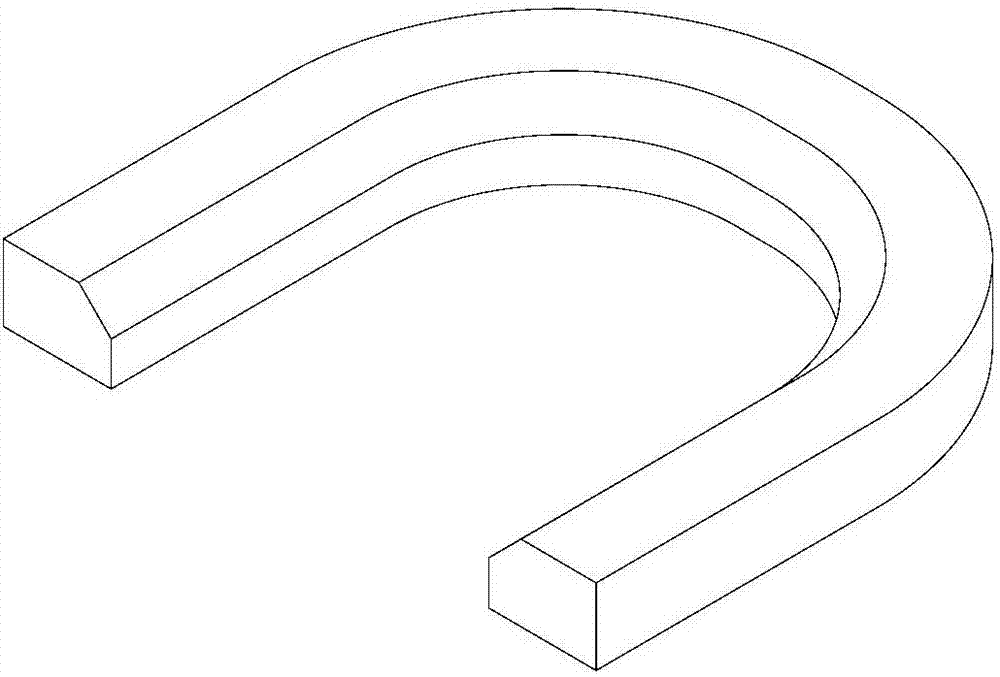
A progressive stamping die for u-shaped parts
A stamping forming and progressive technology, which is applied in the direction of forming tools, manufacturing tools, metal processing equipment, etc., can solve the problems of easy damage of the lower die block, difficult removal of parts, and low processing efficiency, so as to reduce the number of machines and personnel, The effect of ensuring machining accuracy and improving production efficiency
- Summary
- Abstract
- Description
- Claims
- Application Information
AI Technical Summary
Problems solved by technology
Method used
Image

Examples
Embodiment Construction
[0028] Specific embodiments of the present invention will be described in detail below in conjunction with the accompanying drawings.
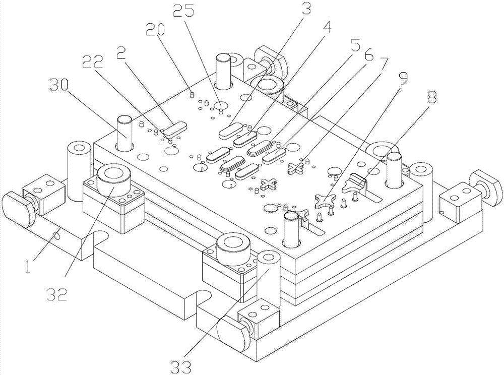
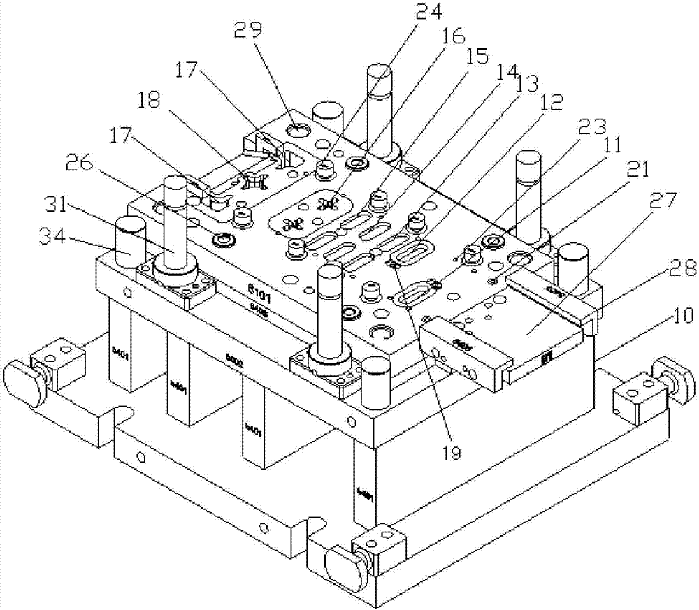
[0029] Such as Figure 2-4 As shown, a progressive stamping die for a U-shaped piece includes an upper die and a lower die. The upper mold includes an upper mold base 1, and the upper mold base 1 is sequentially provided with a waist-shaped left punch 2 and a right punch with the same shape as the left punch 2 from the feed end. Head 3, a pair of first positioning blocks 4 with the same shape as the left punch 2, a pair of waist-shaped hole-shaped forming punches 5, a pair of second positioning blocks 6 with the same shape as the left punch 2 , A pair of small cross punches 7, Dividing punch group. The distance between the left punch 2 and the right punch 3 along the feeding direction is two feeding lengths, the distance between the first positioning block 4 and the forming punch 5, and the distance between the forming punch 5 and the second...
PUM
 Abstract
Description
Claims
Application Information
 - R&D
- Intellectual Property
- Life Sciences
- Materials
- Tech Scout
- Unparalleled Data Quality
- Higher Quality Content
- 60% Fewer Hallucinations
Browse by: Latest US Patents, China's latest patents, Technical Efficacy Thesaurus, Application Domain, Technology Topic, Popular Technical Reports.
© 2025 PatSnap. All rights reserved.Legal|Privacy policy|Modern Slavery Act Transparency Statement|Sitemap|About US| Contact US: help@patsnap.com