
Airbag module with control unit

A control device, airbag technology, applied in transportation and packaging, pedestrian/occupant safety arrangement, vehicle components, etc., can solve problems such as difficulty in implementation

Active Publication Date: 2019-04-12
AUTOLIV DEV AB
View PDF11 Cites 0 Cited by
  • Summary
  • Abstract
  • Description
  • Claims
  • Application Information

AI Technical Summary

Problems solved by technology

The downside here is that the second case and the exhaust have to be directly next to each other, which is often difficult to achieve

Method used


Image

  • Airbag module with control unit
  • Airbag module with control unit
  • Airbag module with control unit

Examples


Embodiment Construction

[0026] First, the invention will be explained on the basis of an application example in which the deflation of an airbag is controlled.

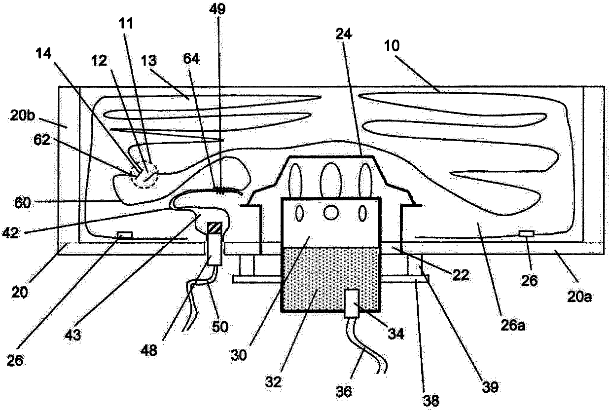
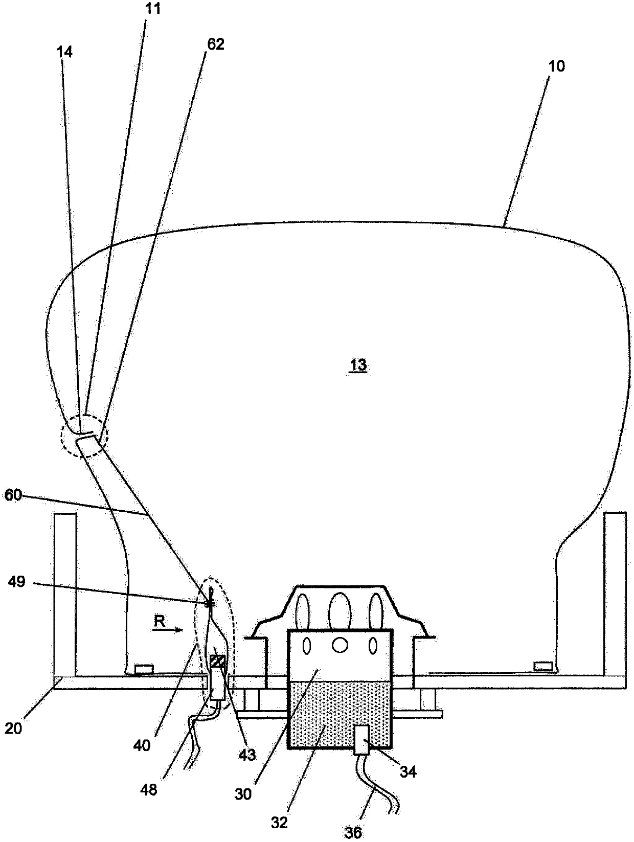
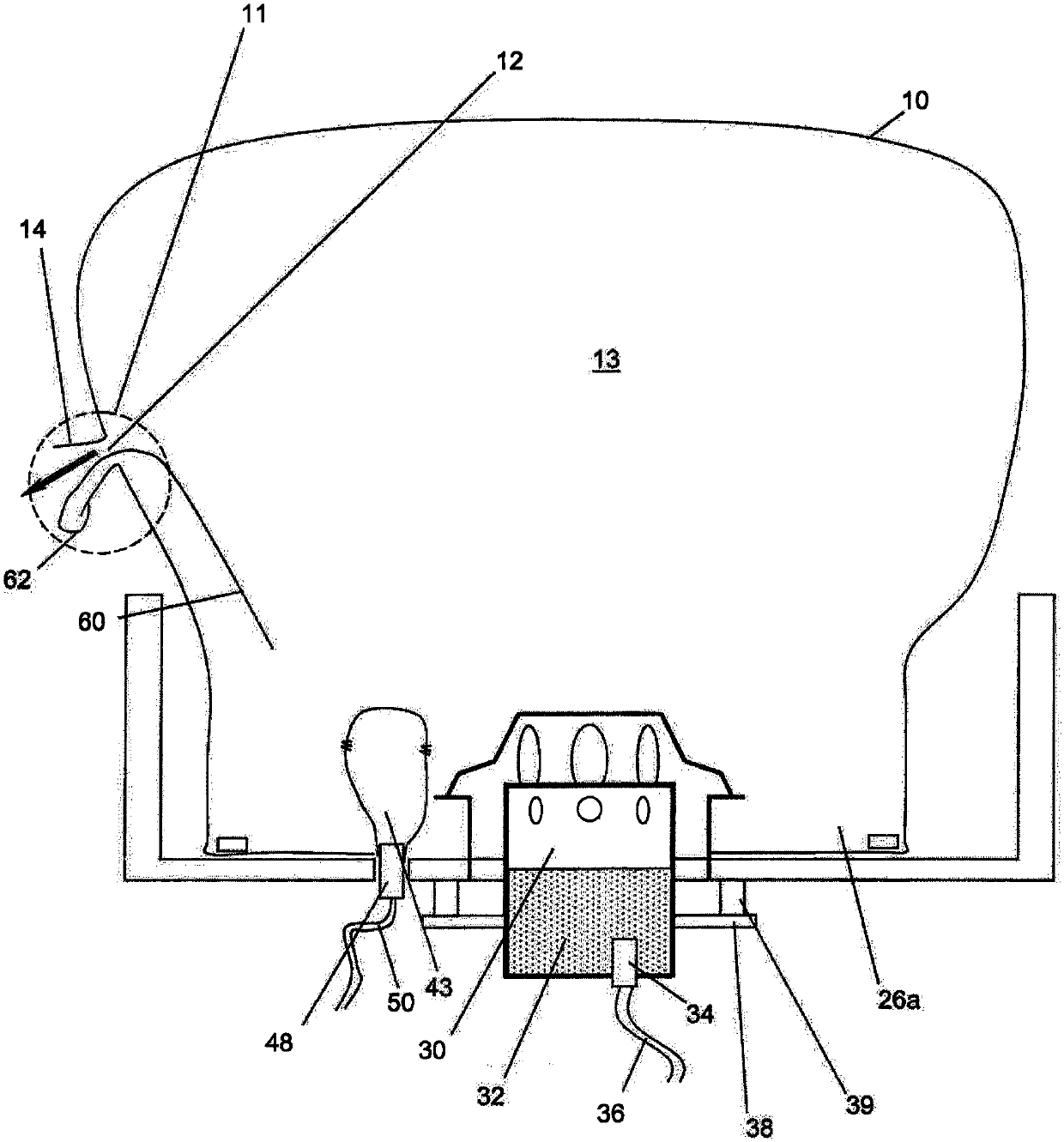
[0027] Figures 1 to 3 A front airbag module is shown, that is to say a driver's airbag module for installation in the hub region of the steering wheel. The airbag module is basically constructed in a conventional manner: that is to say, it has a housing 20 with a housing wall 20 b and a housing bottom 20 a, in the initial state, referred to here as the first housing 10 The airbag cover is folded into the housing. The first housing 10 surrounds a first gas chamber 13 . The first casing 10 is held on the housing bottom 20 a by means of a retaining ring 26 . A first inflatable, i.e. a gas generator 30 is used to fill the first gas chamber, which in the illustrated embodiment extends through an opening 22 in the housing bottom 20a into the interior of the housing 20 and from there to In the first gas chamber 13 . The gas generator 30 has a...


PUM


Abstract

The invention relates to an airbag module comprising: a first casing surrounding a first gas chamber, a first inflator for filling the first gas chamber, and at least one venting or second valve for actively controlling the first gas chamber. A housing-shaped control device. Here the control device has a second casing (42) surrounding a second gas chamber surrounded by a permanent edge connection and a gas source for filling the second gas chamber, and the control device The state of the gas is changed by filling the second gas chamber with the gas source. In order to provide great structural and functional flexibility, the control device also comprises a control element, for example in the form of a drawstring (60), the first end of which is at least indirectly permanently connected to the first casing , the second end of the control element is sewn to the second casing (42) by a tear seam (49) in the unfilled state of the second gas chamber and to the first casing (42) in the filled state of the second gas chamber. The second casing (42) is disengaged, and the tear seam (49) contacts or intersects the edge connection at two points, so that the tear seam divides the unfilled second gas chamber into two separated by the tear seam. Area (43a, 43b).

Description

technical field [0001] The invention relates to an airbag module with a control device. Background technique [0002] Almost all airbags, especially all frontal airbags, have an exhaust device through which gas can escape from the gas chamber (hereinafter referred to as the first gas chamber) surrounded by the outer casing of the airbag—once it reaches the person to be protected. time-escape so that the kinetic energy of the person to be protected is dissipated and the person to be protected is not simply bounced back by the airbag cover of the airbag. In the simplest case, such an exhaust is simply an air outlet, in particular an air outlet in the airbag housing. [0003] In order to be able to take into account different accident situations and / or the weight of the person to be protected, control devices for influencing the shape of the airbag or the pressure in the gas chamber are known in the prior art. If the shape of the airbag is to be controlled, a detachable restr...

Claims


Application Information

Patent Timeline
Patent Type & Authority Patents(China)
IPC IPC(8): B60R21/2342B60R21/2338
CPCB60R21/2342B60R2021/23384B60R2021/2642B60R21/2338B60R21/239B60R21/268B60R2021/2395B60R2021/2685
Inventor M·哈斯K·马萨内兹托马斯·赖特尔安德烈亚斯·古根贝格尔
Owner AUTOLIV DEV AB
Learn More