
Self-destruction disposable injector

A one-time, self-destructing technology, applied in the field of syringes, can solve the problems of non-reusable, non-injection and waste of syringes, and achieve the effect of avoiding recycling

Inactive Publication Date: 2008-11-12
应继水
View PDF5 Cites 0 Cited by
  • Summary
  • Abstract
  • Description
  • Claims
  • Application Information

AI Technical Summary

Problems solved by technology

This kind of syringe also needs manual operation to destroy, which is not very convenient. If the push rod is not broken due to operator negligence, the syringe may still be used repeatedly
And this kind of syringe has greater resistance when advancing
[0003] In the Chinese patent No. 96221160.5, the name is a destructive disposable syringe, which discloses a structure in which a destructive area is set on the gasket at the face end of the push rod, and a destructive body is set at the bottom of the syringe, so that when the piston is pushed to inject , the destructive body set at the bottom pierces the destructive area, and the destructive area produces tearing and air leakage, so no negative pressure can be generated in the piston chamber and cannot be reused. The problem of reuse, but when the damaged body is destroyed in the damaged area, the tear line in the damaged area is irregular, and at the same time of the damage, air leakage occurs, so the syringe of the syringe cannot be injected completely, resulting in a certain amount of waste

Method used


Image

  • Self-destruction disposable injector
  • Self-destruction disposable injector
  • Self-destruction disposable injector

Examples


Embodiment 1

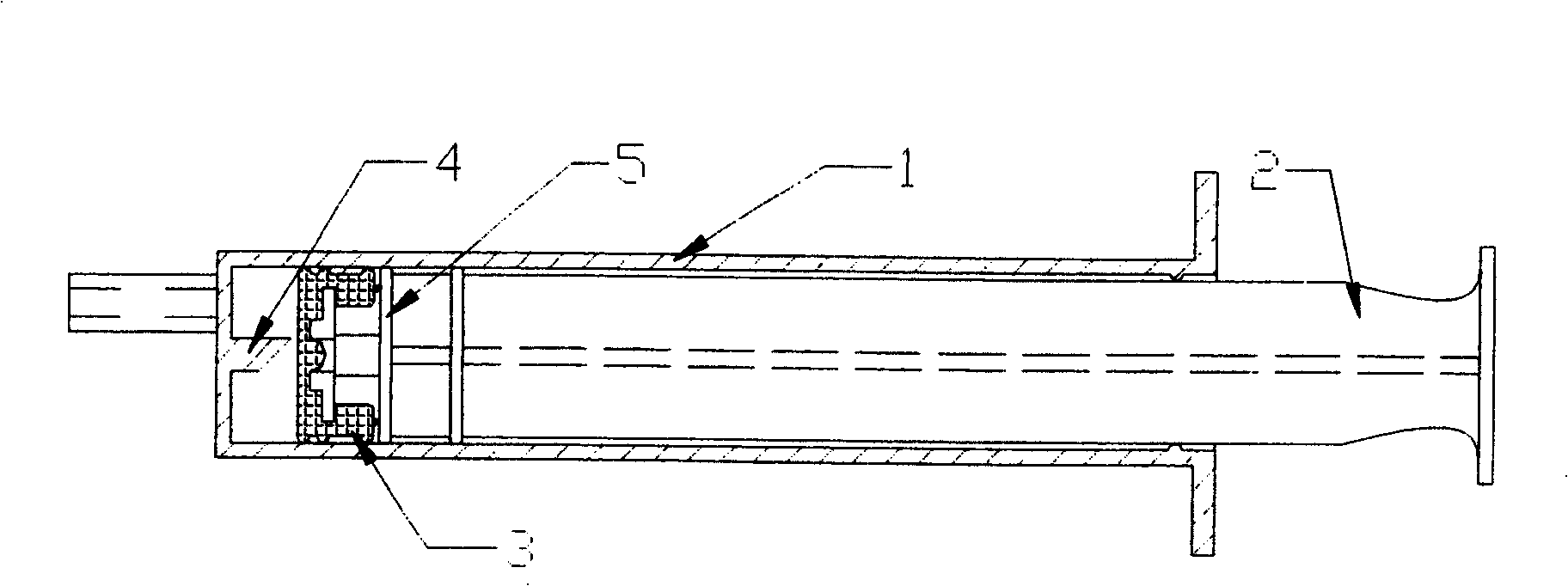
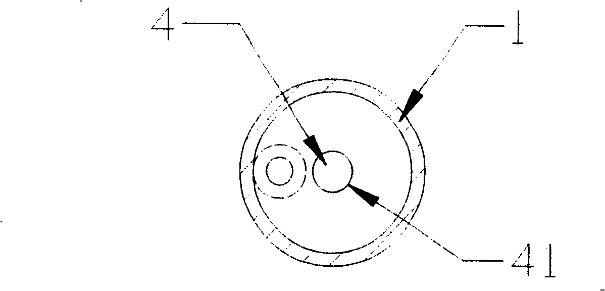
[0023] refer to figure 1 , image 3 and Figure 4 , a self-destructing disposable syringe, comprising a syringe 1 and an injection push rod 2 capable of sliding in the syringe 1, a piston 5 is arranged at the end of the injection push rod 2 located in the syringe 1, A gasket 3 is provided on the piston 5 , a protrusion 4 for destroying the gasket 3 is provided at the bottom of the syringe 1 , and a cavity 51 for the protrusion 4 to enter is provided on the piston 5 .

[0024] The above-mentioned protrusion 4 is a knife, so that it is easier to destroy the sealing gasket 3 after the syringe is used for one-time use. The knife can be selected in many ways. There is a protrusion with a cutting edge. The protrusion 4 in this embodiment is a cylinder and its top surface is a slope, and the intersection line between the cylinder and the top surface is a cutting edge. The top surface of the cylinder is not perpendicular to the axis of the cylinder, for example: the angle between t...

Embodiment 2

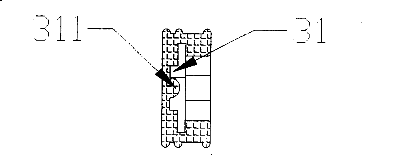
[0027] refer to Figure 5 , Image 6 as well as Figure 7 , a self-destructing disposable syringe, comprising a syringe 1 and an injection push rod 2 capable of sliding in the syringe 1, a piston 5 is arranged at the end of the injection push rod 2 located in the syringe 1, The piston 5 is provided with a gasket 3, the bottom of the syringe 1 is provided with a protrusion 4 for destroying the gasket 3, and the piston 5 is provided with a cavity 51 for the protrusion 4 to enter, and the protrusion 4 is Cutter, this cutter can carry out multiple choices (referring to embodiment 1), and the projection 4 of present embodiment is the cylindrical cutting cutter that is used to destroy gasket 3, is provided with in the cavity 51 of piston 5 and can be connected with cylindrical cutting tool. The column 53 (referring to Figure 7 ), the outer bottom surface of the syringe 1 is provided with a depression 11 and the depression 11 is opposite to the bottom of the protrusion 4 in the s...


PUM


Abstract

The invention discloses a self-destroying disposal injector, comprising syringe and injection push bar sliding inside syringe. The front end of injection push bar is equipped with a piston, piston is equipped with a sealing gasket, the bottom of syringe is equipped with a projection for destroying sealing gasket, and a cave for said projection entrance is equipped on piston. The injection push bar anchors the piston to move in bottom of syringe, and contacts with projection in bottom of syringe after injection, the sealing gasket is deformed and destroyed, so the injector is destroyed and avoids reuse.

Description

technical field [0001] The invention relates to a syringe, in particular to a self-destruct disposable syringe. Background technique [0002] At present, due to the existence of many infectious diseases, patients often use syringes when injecting. In order to prevent cross-infection of syringes, disposable syringes have been promoted. Although there are disposable syringes, due to human reasons, they are often reused, causing cross-infection. Therefore, people have invented a self-destructing disposable syringe, that is, a syringe that is destroyed after the syringe is used, so as to achieve the purpose of ensuring one-time use. These self-destructing disposable syringes generally include a push rod, a syringe and a piston. It is provided with a concave dangerous section on the push rod. After the injection, the push rod is pulled out to break the push rod from the dangerous section Destroy the syringe. This syringe also needs to be destroyed by manual operation, which i...

Claims


Application Information

Patent Timeline
Patent Type & Authority Patents(China)
IPC IPC(8): A61M5/50A61M5/315A61M5/178
Inventor 应继水陈钱权徐爱荣周王汉杨南洲
Owner 应继水
Learn More